Adsense HTML/JavaScript

Showing posts with label Adafruit CircuitPython Library Bundle. Show all posts

Friday, July 22, 2022

Display on I2C SSD1327 grayscale OLED with Arduino Nano RP2040 Connect/CircuitPython

Exercise to display on I2C SSD1327 grayscale OLED with Arduino Nano RP2040 Connect/CircuitPython 7.3.2.


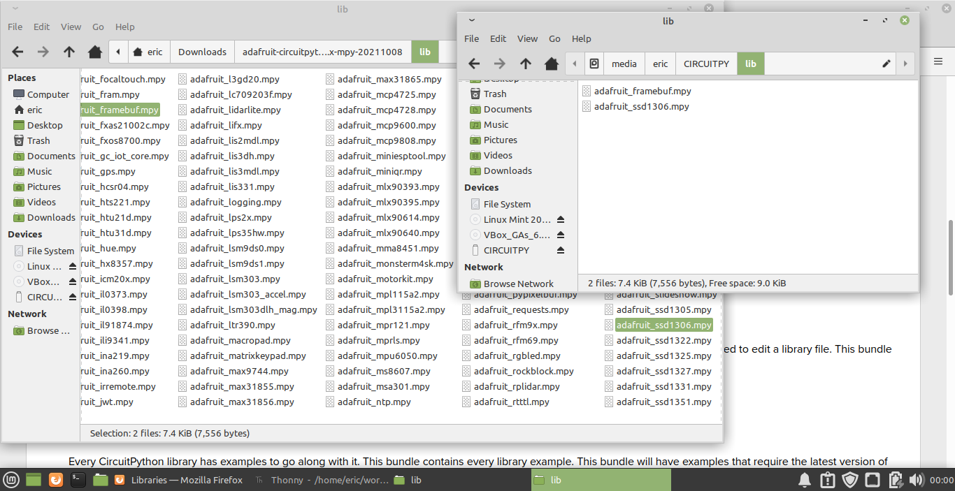
CircuitPython Libraries is needed, visit https://circuitpython.org/libraries to download.

The default I2C pins assigned for Arduino Nano RP2040 Connect/CircuitPython are:
SDA - A4
SCL - A5

The I2C address of my no-brand SSD1327 OLED is 0x3C.


cpyNrp2040_i2c_test.py, I2C test code to I2C pins and address.
import board

i2c = board.I2C()

print("SDA :", board.SDA)
print("SCL :", board.SCL)

while not i2c.try_lock():
    pass

print([hex(x) for x in i2c.scan()])
i2c.unlock()


cpyNrp2040_ssd1327_ani.py
"""
Arduino Nano RP2040 Connect/CircuitPython
128x128 I2C ssd1327 OLED support grayscale
- with something animation.

CircuitPython lib need,
have to be copied to CircutPytho device's /lib:
- adafruit_ssd1327.mpy
- adafruit_display_text folder
- adafruit_display_shapes folder
"""

import time
import board
import displayio
import adafruit_ssd1327
import terminalio
from adafruit_display_text import label
from adafruit_display_shapes.roundrect import RoundRect
from adafruit_display_shapes.rect import Rect

import sys, os

displayio.release_displays()

# print system info
print(board.board_id)
print(sys.implementation[0] + ' ' +
      str(sys.implementation[1][0]) +'.'+
      str(sys.implementation[1][1]) +'.'+
      str(sys.implementation[1][2]))
print("=====================================")
info = sys.implementation[0] + ' ' + \
       os.uname()[3] + '\n' + \
       'run on ' + os.uname()[4]
print(info)
print("=====================================")
print(adafruit_ssd1327.__name__,
      adafruit_ssd1327.__version__)

# Use for I2C
i2c = board.I2C()
#display_bus = displayio.I2CDisplay(i2c, device_address=0x3D)
display_bus = displayio.I2CDisplay(i2c, device_address=0x3C)

display_width = display_height = 128

time.sleep(1)
display = adafruit_ssd1327.SSD1327(display_bus,
                                   width=display_width,
                                   height=display_height)

print()
print(display)
print(display.width,"x", display.height)
print()

g = displayio.Group()
color_count = 128
pattern = displayio.Bitmap(display_width,
                           display_height,
                           color_count)
palette = displayio.Palette(color_count)
t = displayio.TileGrid(pattern, pixel_shader=palette)

pattern.fill(color_count-1)

#init palette
for i in range(color_count):
    component = i * 255 // (color_count - 1)
    #print(component)
    palette[i] = component << 16 | component << 8 | component
    
    """
    print(i, ' - ' ,
          component,":",
          hex(component << 16),
          hex(component << 8),
          hex(component))
    """

g.append(t)

display.show(g)

time.sleep(1)

for i in range(color_count):
    for z in range(i+1):
        pattern[z, 0] = i
        pattern[z, i] = i
        pattern[0, z] = i
        pattern[i, z] = i
    #for y in range(i+1):
    #    pattern[0, y] = i
    #    pattern[i, y] = i

    #time.sleep(0.2)

time.sleep(1)

#================================================
#reverse palette
for i in range(color_count):
    component = i * 255 // (color_count - 1)
    palette[color_count-1-i] = (
        component << 16 | component << 8 | component)
    
time.sleep(3)

#re-reverse palette
for i in range(color_count):
    component = i * 255 // (color_count - 1)
    palette[i] = (
        component << 16 | component << 8 | component)
    
time.sleep(1)
#================================================
#prepare to animate somethin
group_ani = displayio.Group(scale=1)
group_ani.x = 0
group_ani.y = 0
label_ani = label.Label(terminalio.FONT,
                        text="  hello  ",
                        color=0xFFFFFF)
label_ani.anchor_point = (0.0, 0.0)
label_ani.anchored_position = (0, 0)
label_ani_width = label_ani.bounding_box[2]
label_ani_height = label_ani.bounding_box[3]
shape_ani = RoundRect(x=0, y=0,
                       width=label_ani_width,
                       height=label_ani_height,
                       r=6,
                       fill=0x000000,
                       outline=0xFFFFFF, stroke=1)

group_ani.append(shape_ani)
group_ani.append(label_ani)
g.append(group_ani)
#================================================
#prepare to somethin on fixed position
group_fix = displayio.Group(scale=2)
group_fix.x = 70
group_fix.y = 20
label_fix = label.Label(terminalio.FONT,
                        text=":)",
                        color=0xFFFFFF)
label_fix.anchor_point = (0.0, 0.0)
label_fix.anchored_position = (0, 0)
label_fix_width = label_fix.bounding_box[2]
label_fix_height = label_fix.bounding_box[3]
shape_fix = Rect(x=0, y=0,
                 width=label_fix_width,
                 height=label_fix_height,
                 fill=0x000000,
                 outline=0xFFFFFF, stroke=1)

group_fix.append(shape_fix)
group_fix.append(label_fix)
g.append(group_fix)
#=== loop of animation ===
aniXMove = +1
aniYMove = +1
aniXLim = display_width - 1 - label_ani_width
aniYLim = display_height - 1 - label_ani_height

NxAniMs = time.monotonic() + 3

while True:
    time.sleep(0.05)
    
    if time.monotonic() > NxAniMs:
        NxAniMs = time.monotonic() + 1
        
    #Move Temperate group
    x = group_ani.x + aniXMove
    group_ani.x = x
    if aniXMove > 0:
        if x >= aniXLim:
            aniXMove = -1
    else:
        if x <= 0:
            aniXMove = +1
            
    y = group_ani.y + aniYMove
    group_ani.y = y
    if aniYMove > 0:
        if y > aniYLim:
            aniYMove = -1
    else:
        if y <= 0:
            aniYMove = +1

#================================================
            
print("~ bye ~")


cpyNrp2040_ssd1327_ani2.py
"""
Arduino Nano RP2040 Connect/CircuitPython
128x128 I2C ssd1327 OLED support grayscale
- Change background bitmap by changing palette

CircuitPython lib need,
have to be copied to CircutPytho device's /lib:
- adafruit_ssd1327.mpy
- adafruit_display_text folder
- adafruit_display_shapes folder
"""

import time
import board
import displayio
import adafruit_ssd1327
import terminalio
from adafruit_display_text import label
from adafruit_display_shapes.circle import Circle

import sys, os

displayio.release_displays()

# print system info
print(board.board_id)
print(sys.implementation[0] + ' ' +
      str(sys.implementation[1][0]) +'.'+
      str(sys.implementation[1][1]) +'.'+
      str(sys.implementation[1][2]))
print("=====================================")
info = sys.implementation[0] + ' ' + \
       os.uname()[3] + '\n' + \
       'run on ' + os.uname()[4]
print(info)
print("=====================================")
print(adafruit_ssd1327.__name__,
      adafruit_ssd1327.__version__)

# Use for I2C
i2c = board.I2C()
#display_bus = displayio.I2CDisplay(i2c, device_address=0x3D)
display_bus = displayio.I2CDisplay(i2c, device_address=0x3C)

display_width = display_height = 128

time.sleep(1)
display = adafruit_ssd1327.SSD1327(display_bus,
                                   width=display_width,
                                   height=display_height)

print()
print(display)
print(display.width,"x", display.height)
print()

g = displayio.Group()

# I define the OLED in 16 grayscale,
# hardcode defined in a list (instead of by calculating),
# such that you can manual set according to your need.
grayscale = [0x00, 0x10, 0x20, 0x30,
             0x40, 0x50, 0x60, 0x70,
             0x80, 0x90, 0xA0, 0xB0,
             0xC0, 0xD0, 0xE0, 0xF0]
grayscale_count = len(grayscale)
#print([hex(g) for g in grayscale])
#print(grayscale_count)

#back ground have on color only
bg_color_count = 1
bg_bitmap = displayio.Bitmap(display_width,
                           display_height,
                           bg_color_count)
bg_palette = displayio.Palette(bg_color_count)
t = displayio.TileGrid(bg_bitmap,
                       pixel_shader=bg_palette)

bg_bitmap.fill(0)

print()
print("default bg_palette without init")
print([hex(p) for p in bg_palette])
print()

#================================================
#prepare to display grayscale
group_gray = displayio.Group(scale=1)
group_gray.x = 0
group_gray.y = 0
label_gray = label.Label(terminalio.FONT,
                        text="    ",
                        color=0xB0B0B0)
label_gray.anchor_point = (0.0, 0.0)
label_gray.anchored_position = (10, 10)
label_gray_width = label_gray.bounding_box[2]
label_gray_height = label_gray.bounding_box[3]

shape_gray = Circle(x0=0,
                    y0=0,
                    r=80,
                    fill=0xFFFFFF,
                    outline=0x000000,
                    stroke=3)

group_gray.append(shape_gray)
group_gray.append(label_gray)

#====================================

g.append(t)
g.append(group_gray)

display.show(g)

for gs in grayscale:
    
    bg_palette[0] = (gs << 16
                     | gs << 8
                     | gs)
    
    # you can try to remove any elements
    # to check the effect.
    #bg_palette[0] = (0
    #                 | gs << 8
    #                 | 0)
    
    #print([hex(p) for p in bg_palette])
    label_gray.text = str(hex(bg_palette[0]))
    time.sleep(0.5)

time.sleep(1)

#================================================
            
print("~ bye ~")


Monday, April 4, 2022

CircuitPython BLE UART between XIAO BLE Sense and ESP32-C3/S3

It's a exercise of CircuitPython to implement BLE UART between server and client. All boards are flashed with CircuitPython 7.2.4 firmware, with adafruit_ble 8.2.3.


The server side run on Seeed XIAO BLE Sense (nRF52840) + Expansion board. The code modified from Adafruit CircuitPython ble_uart_echo_test.py example, or here, setup BLE UART Server, but display on SSD1306 I2C OLED instead of echo back.

The client side run on Ai-Thinker NodeMCU ESP-C3-32S-Kit and Espressif ESP32-S3-DevKitC-1. The code modified from ble_uart_echo_client.py, or here. The user enter text in REPL to send to server side and display on SSD1306 I2C OLED.

un-solved issue:

If server side offline and the BLE link disconnected, then server side online again and re-connected, the client side will fail; tested on both ESP-C3-32S-Kit and ESP32-S3-DevKitC-1.


Exercise code:

cpyXIAOBLE_ble_uart_server_ssd1306.py, run on server side.
"""
Run CircuitPython 7.2.4 on
Seeed XIAO nRF52840 Sense with nRF52840 + Expansion Board.
Modified from ble_uart_echo_test.py.
Act as BLE server, wait connection and
display received line on ssd13106 OLED.

libs need:
- adafruit_ble folder
- adafruit_displayio_ssd1306.mpy
"""
import os
import sys
import board
import busio
import displayio
import adafruit_displayio_ssd1306

from adafruit_ble import BLERadio
from adafruit_ble.advertising.standard import ProvideServicesAdvertisement
from adafruit_ble.services.nordic import UARTService
from adafruit_ble import __name__ as BLE_NAME
from adafruit_ble import __version__ as BLE_VERSION

displayio.release_displays()

# Create the I2C interface and display object of SSD1306_I2C.
i2c = busio.I2C(board.SCL, board.SDA)

ssd1306_i2c_addr = 60
display_width =128
display_height = 64
display_bus = displayio.I2CDisplay(
    i2c, device_address=ssd1306_i2c_addr)
display = adafruit_displayio_ssd1306.SSD1306(
    display_bus, width=display_width, height=display_height)

# with displayio initialized, and have nothing displayed.
# displayio act like a REPL terminal.
# anything print() will be displayed on displayio also.

print("=================================================")
info = sys.implementation[0] + ' ' + os.uname()[3] + '\n' + \
       'run on ' + os.uname()[4]
print(info)
print("=================================================")
print(BLE_NAME, ":", BLE_VERSION)
print("=================================================")
print(adafruit_displayio_ssd1306.__name__, adafruit_displayio_ssd1306.__version__)
print("SCL: ", board.SCL)
print("SDA: ", board.SDA)

print(display)
print("display.width x height: ",
      display.width, " x ", display.height)
#=================================

ble = BLERadio()
uart = UARTService()
advertisement = ProvideServicesAdvertisement(uart)

#=== scroll up to print screen ===
print()
print()
print()
print(" ---- hello ----")

while True:
    ble.start_advertising(advertisement)
    print("Waiting to connect")
    while not ble.connected:
        pass
    print("Connected")
    while ble.connected:
        s = uart.readline()
        if s:
            print(s.decode())
            uart.write(s)

print("~ bye ~")

cpyESP32x3_ble_uart_client_repl.py, run on client side.
"""
Run CircuitPython 7.2.4 on
AITHinker ESP32-C3S_Kit with ESP32-C3FN4/ESP32-S3-DevKitC-1-N8R8 with ESP32S3.
Modified from ble_uart_echo_client.py.
Act as BLE client, connect to server,
get user input from REPL and send to server.

libs need:
- adafruit_ble folder
"""
import os
import sys
import time

from adafruit_ble import BLERadio
from adafruit_ble.advertising.standard import ProvideServicesAdvertisement
from adafruit_ble.services.nordic import UARTService
from adafruit_ble import __name__ as BLE_NAME
from adafruit_ble import __version__ as BLE_VERSION

print("=================================================")
info = sys.implementation[0] + ' ' + os.uname()[3] + '\n' + \
       'run on ' + os.uname()[4]
print(info)
print("=================================================")
print(BLE_NAME, ":", BLE_VERSION)
print("=================================================")

ble = BLERadio()
while True:
    while ble.connected and any(
        UARTService in connection for connection in ble.connections
    ):
        for connection in ble.connections:
            if UARTService not in connection:
                continue
            
            uart = connection[UARTService]
            
            # input() will block the code.
            # if connection lost while waiting user input,
            # ConnectionError will thrown in uart.write()
            userinput = input("\nEnter something: ")
            print(userinput)
            
            try:
                uart.write(userinput)
            except ConnectionError as exc:
                print("ConnectionError:", exc)
            
    print("disconnected, scanning")
    for advertisement in ble.start_scan(ProvideServicesAdvertisement, timeout=1):
        if UARTService not in advertisement.services:
            continue
        ble.connect(advertisement)
        print("connected")
        break
    ble.stop_scan()


It you cannot open two Thonny instance, read last post How to open dual Thonny instance.


Wednesday, March 30, 2022

XIAO BLE Sense (nRF52840)/CircuitPython generate QR Code and display on SSD1306 I2C OLED

adafruit_miniqr is a A non-hardware dependant miniature QR generator library.

Once Adafruit CircuitPython Libraries downloaded (as shown in last post's video), there are two examples miniqr_simpletest.py and miniqr_displaytest.py in extracted examples foler, or can be found here.

cpyX_miniqr_ssd1306.py is modified from miniqr_displaytest.py, to run on Seeed XIAO BLE Sense (nRF52840)/CircuitPython 7.2.3 to generate QR Code and display on SSD1306 I2C OLED.


cpyX_miniqr_ssd1306.py
"""
CircuitPython 7.2.3 exercise run on
Seeed XIAO nRF52840 Sense with nRF52840
- generate QR Code using adafruit_miniqr
- display on SSD1306 I2C OLED

lib needed:
- adafruit_displayio_ssd1306.mpy
- adafruit_miniqr.mpy
"""

import os
import sys
import board
import busio
import displayio
import adafruit_displayio_ssd1306
import adafruit_miniqr

displayio.release_displays()

print("=================================================")
info = sys.implementation[0] + ' ' + os.uname()[3] + '\n' + \
       'run on ' + os.uname()[4]
print(info)
print("=================================================")
print(adafruit_miniqr.__name__,
      adafruit_miniqr.__version__)
print(adafruit_displayio_ssd1306.__name__,
      adafruit_displayio_ssd1306.__version__)

# Create the I2C interface and display object of SSD1306_I2C.
i2c = busio.I2C(board.SCL, board.SDA)

ssd1306_i2c_addr = 60
display_width =128
display_height = 64
display_bus = displayio.I2CDisplay(
    i2c, device_address=ssd1306_i2c_addr)
display = adafruit_displayio_ssd1306.SSD1306(
    display_bus, width=display_width, height=display_height)

# remark by Erik:
# base on my testing on 128x64 SSD1306,
# A full white background can improve the recognition
# so I add a background in white
background_bitmap = displayio.Bitmap(display_width,
                                     display_height, 1)
background_palette = displayio.Palette(1)
background_palette[0] = 0xFFFFFF
bg_sprite = displayio.TileGrid(background_bitmap,
                               pixel_shader=background_palette,
                               x=0, y=0)

def bitmap_QR(matrix):

    # monochome (2 color) palette
    BORDER_PIXELS = 2

    # bitmap the size of the screen, monochrome (2 colors)
    bitmap = displayio.Bitmap(
        matrix.width + 2 * BORDER_PIXELS,
        matrix.height + 2 * BORDER_PIXELS, 2
    )
    # raster the QR code
    for y in range(matrix.height):  # each scanline in the height
        for x in range(matrix.width):
            if matrix[x, y]:
                bitmap[x + BORDER_PIXELS, y + BORDER_PIXELS] = 1
            else:
                bitmap[x + BORDER_PIXELS, y + BORDER_PIXELS] = 0
    return bitmap


qr = adafruit_miniqr.QRCode(qr_type=3,
                            error_correct=adafruit_miniqr.L)
qr.add_data(b"http://embedded-things.blogspot.com/")
qr.make()

# generate the 1-pixel-per-bit bitmap
qr_bitmap = bitmap_QR(qr.matrix)
# We'll draw with a classic black/white palette
palette = displayio.Palette(2)
palette[0] = 0xFFFFFF
palette[1] = 0x000000
# we'll scale the QR code as big as the display can handle
scale = min(
    display_width // qr_bitmap.width,
    display_height // qr_bitmap.height
)
# then center it!
pos_x = int(((display_width / scale) - qr_bitmap.width) / 2)
pos_y = int(((display_height / scale) - qr_bitmap.height) / 2)
qr_img = displayio.TileGrid(qr_bitmap,
                            pixel_shader=palette,
                            x=pos_x, y=pos_y)

splash = displayio.Group(scale=scale)
splash.append(bg_sprite)
splash.append(qr_img)
display.show(splash)

# Hang out forever
while True:
    pass

Tuesday, March 29, 2022

Seeed XIAO BLE Sense (nRF52840)/CircuitPython 7.2.3 display on SSD1306 I2C OLED

Updated@2024-01-31

Somethings in displayio changed in CircuitPython 9, check the updated on ESP32-S3:
Waveshare ESP32-S3-Zero/CircuitPython 9.0.0-beta.0 to display on 128x64 SSD1306 I2C OLED


In CircuitPython, to display on SSD1306, there are two approach:
- framebuf  (using adafruit_ssd1306/adafruit_framebuf)
- displayio (using adafruit_displayio_ssd1306)

The video demo Seeed XIAO BLE Sense (nRF52840)/CircuitPython 7.2.3 display on Seeeduino XIAO Expansion board onboard SSD1306 I2C OLED using both framebuf  and displayio.


Exercise code:

cpyX_i2c.py
"""
Seeed XIAO nRF52840 Sense with nRF52840/CircuitPython 7.2.3
- verify I2C SCL/SDA pin
- Scan available I2C devices
"""

import os
import sys
import busio
import board

print("=================================================")
info = sys.implementation[0] + ' ' + os.uname()[3] + '\n' + \
       'run on ' + os.uname()[4]
print(info)
print("=================================================")

print("SCL: ", board.SCL)
print("SDA: ", board.SDA)
i2c = board.I2C()
print(i2c)
print()

#Scan I2C devices
if(i2c.try_lock()):
    print("i2c.scan(): " + str(i2c.scan()))
    i2c.unlock()
print()

cpyX_ssd1306.py
"""
CircuitPython 7.2.3 exercise run on
Seeed XIAO nRF52840 Sense with nRF52840
- display on SSD1306 I2C OLED
- using adafruit_ssd1306

lib needed:
- adafruit_ssd1306.mpy
- adafruit_framebuf.mpy
- font5x8.bin (from examples folder,
  to current folder in CircuitPython device)
"""

import os
import sys
import board
import busio
import time

import adafruit_ssd1306

# Create the I2C interface and display object of SSD1306_I2C.
i2c = busio.I2C(board.SCL, board.SDA)
display = adafruit_ssd1306.SSD1306_I2C(128, 64, i2c)

print("=================================================")
info = sys.implementation[0] + ' ' + os.uname()[3] + '\n' + \
       'run on ' + os.uname()[4]
print(info)
print("=================================================")
print(adafruit_ssd1306.__name__, adafruit_ssd1306.__version__)
print("SCL: ", board.SCL)
print("SDA: ", board.SDA)

print(display)
print("display.width x height: ",
      display.width, " x ", display.height)
    
display.fill(0)
display.show()
time.sleep(1)
display.fill(1)
display.show()
time.sleep(1)

display.fill(0)


strSys = sys.implementation[0] + ' ' + \
         str(sys.implementation[1][0]) +'.'+ \
         str(sys.implementation[1][1]) +'.'+ \
         str(sys.implementation[1][2])

strLib = adafruit_ssd1306.__name__ + '\n' \
         + adafruit_ssd1306.__version__

def drawInfo():
    display.text(strSys, 0, 0, 1)
    display.text(strLib, 0, 10, 1)
    display.text(os.uname()[4], 0, 30, 1)
    display.text("SSD1306", 0, 40, 1)
    strResolution = str(display.rotation) + ' : ' \
                    + str(display.width) + ' x ' \
                    + str(display.height)
    display.text(strResolution, 0, 50, 1)
    
for r in range(0, 4):
    display.fill(0)
    display.rotation = r
    drawInfo()
    display.show()
    time.sleep(5)

display.rotation = 0

#draw rectangle
display.fill(0)
display.rect(0, 0, display.width, display.height, 1)
display.show()
time.sleep(1)
display.fill(0)
display.fill_rect(0, 0, display.width, display.height, 1)
display.show()
time.sleep(1)

#draw circle
display.fill(0)
if display.width > display.height:
    r = (int)(display.height/2)
else:
    r = (int)(display.width/2)
display.circle((int)(display.width/2),
               (int)(display.height/2), r, 1)
display.show()
time.sleep(1)

display.fill(0)
display.show()

# draw pixels
for y in range(0, display.height, 8):
    for x in range(0, display.width, 8):
        display.pixel(x, y, 1)
        display.show()
time.sleep(1)
display.invert(1)
time.sleep(2)
display.invert(0)
time.sleep(1)

cpyX_displayio_ssd1306.py
"""
CircuitPython 7.2.3 exercise run on
Seeed XIAO nRF52840 Sense with nRF52840
- display on SSD1306 I2C OLED
- using adafruit_displayio_ssd1306

lib needed:
- adafruit_displayio_ssd1306.mpy
- adafruit_display_text folder
"""

import os
import sys
import board
import busio
import time

import displayio
import terminalio
import adafruit_displayio_ssd1306
from adafruit_display_text import label

displayio.release_displays()

# Create the I2C interface and display object of SSD1306_I2C.
i2c = busio.I2C(board.SCL, board.SDA)

ssd1306_i2c_addr = 60
display_width =128
display_height = 64
display_bus = displayio.I2CDisplay(
    i2c, device_address=ssd1306_i2c_addr)
display = adafruit_displayio_ssd1306.SSD1306(
    display_bus, width=display_width, height=display_height)

print("=================================================")
info = sys.implementation[0] + ' ' + os.uname()[3] + '\n' + \
       'run on ' + os.uname()[4]
print(info)
print("=================================================")
print(adafruit_displayio_ssd1306.__name__,
      adafruit_displayio_ssd1306.__version__)
print("SCL: ", board.SCL)
print("SDA: ", board.SDA)

print(display)
print("display.width x height: ",
      display.width, " x ", display.height)
#================================================
# Make the display context
group = displayio.Group()

NUM_OF_COLOR = 2
bitmap = displayio.Bitmap(display_width,
                          display_height,
                          NUM_OF_COLOR)
bitmap_palette = displayio.Palette(NUM_OF_COLOR)
bitmap_palette[0] = 0x000000
bitmap_palette[1] = 0xFFFFFF

tileGrid = displayio.TileGrid(bitmap,
                              pixel_shader=bitmap_palette,
                              x=0, y=0)
group.append(tileGrid)
display.show(group)

time.sleep(1)
bitmap.fill(1)

def range_f(start, stop, step):
    f = start
    while f < stop:
        yield f
        f += step
        
time.sleep(1)
for y in range_f(0, display_height-1, 2):
    for x in range_f(0, display_width-1, 2):
        #print(str(x) + " : " + str(y))
        bitmap[x, y] = 0

time.sleep(1)
#========================================================
# Draw a label
text_group1 = displayio.Group(scale=3, x=0, y=0)
text1 = "Hello"
text_area1 = label.Label(terminalio.FONT,
                         text=text1, color=0xFFFFFF)
text_group1.append(text_area1)
group.append(text_group1)

for xy in range(20):
    time.sleep(0.1)
    text_group1.x=xy
    text_group1.y=xy
#========================================================
#invert palette
time.sleep(1)
bitmap_palette[1] = 0x000000
bitmap_palette[0] = 0xFFFFFF

time.sleep(1)
y = 0
for x in range_f(0, display_width-1, 1):
    bitmap[x, y] = 0
    time.sleep(0.01)
x = display_width-1
for y in range_f(0, display_height-1, 1):
    bitmap[x, y] = 0
    time.sleep(0.01)

y = display_height-1
for x in range_f(0, display_width-1, 1):
    bitmap[x, y] = 0
    time.sleep(0.01)
x = 0
for y in range_f(0, display_height-1, 1):
    bitmap[x, y] = 0
    time.sleep(0.01)

#invert palette
time.sleep(1)
bitmap_palette[0] = 0x000000
bitmap_palette[1] = 0xFFFFFF
#invert palette
time.sleep(1)
bitmap_palette[1] = 0x000000
bitmap_palette[0] = 0xFFFFFF

time.sleep(1)
bitmap.fill(1)
time.sleep(1)
for xy in range(20):
    time.sleep(0.1)
    text_group1.x=xy+20
    text_group1.y=xy+20
time.sleep(1)
print("- bye -")

cpyX_displayio_ssd1306_ani.py
"""
CircuitPython 7.2.3 exercise run on
Seeed XIAO nRF52840 Sense with nRF52840
- display on SSD1306 I2C OLED
- using adafruit_displayio_ssd1306
- with animation

lib needed:
- adafruit_displayio_ssd1306.mpy
- adafruit_display_text folder
- adafruit_display_shapes folder
"""

import os
import sys
import board
import busio
import time

import displayio
import terminalio
import adafruit_displayio_ssd1306
from adafruit_display_text import label
from adafruit_display_shapes.roundrect import RoundRect
from adafruit_display_shapes.rect import Rect

displayio.release_displays()

# Create the I2C interface and display object of SSD1306_I2C.
i2c = busio.I2C(board.SCL, board.SDA)

ssd1306_i2c_addr = 60
display_width =128
display_height = 64
display_bus = displayio.I2CDisplay(
    i2c, device_address=ssd1306_i2c_addr)
display = adafruit_displayio_ssd1306.SSD1306(
    display_bus, width=display_width, height=display_height)

print("=================================================")
info = sys.implementation[0] + ' ' + os.uname()[3] + '\n' + \
       'run on ' + os.uname()[4]
print(info)
print("=================================================")
print(adafruit_displayio_ssd1306.__name__,
      adafruit_displayio_ssd1306.__version__)
print("SCL: ", board.SCL)
print("SDA: ", board.SDA)

print(display)
print("display.width x height: ",
      display.width, " x ", display.height)
#================================================
# Make the display context
group = displayio.Group()

NUM_OF_COLOR = 2
bitmap = displayio.Bitmap(display_width,
                          display_height,
                          NUM_OF_COLOR)
bitmap_palette = displayio.Palette(NUM_OF_COLOR)
bitmap_palette[0] = 0x000000
bitmap_palette[1] = 0xFFFFFF

tileGrid = displayio.TileGrid(bitmap,
                              pixel_shader=bitmap_palette,
                              x=0, y=0)
group.append(tileGrid)
display.show(group)

time.sleep(1)
bitmap.fill(1)

def range_f(start, stop, step):
    f = start
    while f < stop:
        yield f
        f += step
 
time.sleep(1)
for y in range_f(0, display_height-1, 2):
    for x in range_f(0, display_width-1, 2):
        #print(str(x) + " : " + str(y))
        bitmap[x, y] = 0

time.sleep(1)

#========================================================
# Draw a label
text_group1 = displayio.Group(scale=3, x=0, y=0)
text1 = "Hello"
text_area1 = label.Label(terminalio.FONT, text=text1, color=0xFFFFFF)
text_group1.append(text_area1)
group.append(text_group1)

text_group1.x=20
text_group1.y=20
#========================================================
#invert palette
time.sleep(1)
bitmap_palette[1] = 0x000000
bitmap_palette[0] = 0xFFFFFF

time.sleep(1)
y = 0
for x in range_f(0, display_width-1, 1):
    bitmap[x, y] = 0
    time.sleep(0.01)
x = display_width-1
for y in range_f(0, display_height-1, 1):
    bitmap[x, y] = 0
    time.sleep(0.01)

y = display_height-1
for x in range_f(0, display_width-1, 1):
    bitmap[x, y] = 0
    time.sleep(0.01)
x = 0
for y in range_f(0, display_height-1, 1):
    bitmap[x, y] = 0
    time.sleep(0.01)

#================================================
#prepare to animate somethin
group_ani = displayio.Group(scale=1)
group_ani.x = 0
group_ani.y = 0
label_ani = label.Label(terminalio.FONT,
                        text="  hello  ",
                        color=0xFFFFFF)
label_ani.anchor_point = (0.0, 0.0)
label_ani.anchored_position = (0, 0)
label_ani_width = label_ani.bounding_box[2]
label_ani_height = label_ani.bounding_box[3]
shape_ani = RoundRect(x=0, y=0,
                       width=label_ani_width,
                       height=label_ani_height,
                       r=6,
                       fill=0x000000,
                       outline=0xFFFFFF, stroke=1)

group_ani.append(shape_ani)
group_ani.append(label_ani)
group.append(group_ani)
#================================================
#prepare to somethin on fixed position
group_fix = displayio.Group(scale=2)
group_fix.x = 70
group_fix.y = 20
label_fix = label.Label(terminalio.FONT,
                        text=":)",
                        color=0xFFFFFF)
label_fix.anchor_point = (0.0, 0.0)
label_fix.anchored_position = (0, 0)
label_fix_width = label_fix.bounding_box[2]
label_fix_height = label_fix.bounding_box[3]
shape_fix = Rect(x=0, y=0,
                 width=label_fix_width,
                 height=label_fix_height,
                 fill=0x000000,
                 outline=0xFFFFFF, stroke=1)

group_fix.append(shape_fix)
group_fix.append(label_fix)
group.append(group_fix)
#=== loop of animation ===
aniXMove = +1
aniYMove = +1
aniXLim = display_width - 1 - label_ani_width
aniYLim = display_height - 1 - label_ani_height

NxAniMs = time.monotonic() + 3

while True:
    time.sleep(0.05)
    
    if time.monotonic() > NxAniMs:
        NxAniMs = time.monotonic() + 1
        
    #Move Temperate group
    x = group_ani.x + aniXMove
    group_ani.x = x
    if aniXMove > 0:
        if x >= aniXLim:
            aniXMove = -1
    else:
        if x <= 0:
            aniXMove = +1
            
    y = group_ani.y + aniYMove
    group_ani.y = y
    if aniYMove > 0:
        if y > aniYLim:
            aniYMove = -1
    else:
        if y <= 0:
            aniYMove = +1
                        
print("- bye -")
next:
XIAO BLE Sense (nRF52840)/CircuitPython generate QR Code and display on SSD1306 I2C OLED


Monday, March 21, 2022

Arduino Nano RP2040 Connect/CircuitPython + ov7670 cam (incomplete) display on st7789 Display

It's just my exercise running on Arduino Nano RP2040 Connect/CircuitPython 7.2.3, to work with ov7670 cam module and display on ST7789 SPI display.


For the connection between Nano RP2040 Connect and ov7670/st7789, refer to the code listed below.

In my practice, pre-defined SPI MOSI/SCK are assigned to SDA/SCL for ST7789. I2C SCL/SDA are assigned to SCL/SDA for ov7670.

*ov7670 SCL/SDA are I2C-like control pins, pull-up resistors are needed. 2K ohm resistors are used in my exercise.

For the st7789 part, it's very straightforward - just install libraries and run the exercise code.
Libraries adafruit_st7789 and adafruit_display_text are needed.

For ov7670 part, libraries adafruit_st7789 and adafruit_ov7670 are needed. adafruit_ov7670 is a CircuitPython driver for OV7670 cameras.

The problem is in adafruit_ov7670, data_pins is a list of 8 data pins in sequential order.  But I can't find 8 continuous sequence GPIO on Nano RP2040 Connect. As an exercise, GPIO14~21 are assigned to ov7670 d0~d7, GPIO14 is internal connceted to SCK of the onboard ESP32 (U-blox Nina W102), so it's actually no use. So there are only 7 bits in parallel data bus, and ESP32 SCK is mis-used (you should cannot use ESP32 at the same time). That's why I call it "incomplete".

It seem functionally work, as shown in the video. But I don't know any side-effect. It's just my exercise and not suggested, or follow at your own risk.

To list pins name of all GPIOs (include internal), read last post.


cpyNrp2040_spiST7789_320.py
"""
Example of Arduino Nano RP2040 Connect/CircuitPython 7.2.3
to display on 2.0" IPS 240x320 (RGB) screen
with SPI ST7789 driver.

Connection between Nano RP2040 Connect and
the SPI ST7789 IPS screen.

BLK  - 3V3 (backlight, always on)
CS   - A0
DC   - A1
RES  - A2
SDA  - D11 (=MOSI)
SCL  - D13 (=SCK)
VCC  - 3V3
GND  - GND
"""

import os
import sys
import board
import microcontroller
import time
import terminalio
import displayio
import busio
from adafruit_display_text import label
#from adafruit_st7789 import ST7789
import adafruit_st7789

print("=====================================")
info = sys.implementation[0] + ' ' + \
       os.uname()[3] + '\n' + \
       'run on ' + os.uname()[4]
print(info)
print("board_id:", board.board_id)

print("with number of cpu: " +
      str(len(microcontroller.cpus)))
print("=====================================")
print(adafruit_st7789.__name__ + " version: "
      + adafruit_st7789.__version__)

print()

# Release any resources currently in use for the displays
displayio.release_displays()

tft_cs = board.A0
tft_dc = board.A1
tft_res = board.A2
spi_mosi = board.D11
spi_clk = board.D13

"""
classbusio.SPI(clock: microcontroller.Pin,
                MOSI: Optional[microcontroller.Pin] = None,
                MISO: Optional[microcontroller.Pin] = None)
"""
spi = busio.SPI(clock=spi_clk, MOSI=spi_mosi)

display_bus = displayio.FourWire(
    spi, command=tft_dc, chip_select=tft_cs, reset=tft_res
)

display = adafruit_st7789.ST7789(display_bus,
                    width=240, height=320)

# Make the display context
splash = displayio.Group()
display.show(splash)

color_bitmap = displayio.Bitmap(135, 240, 1)
color_palette = displayio.Palette(1)
color_palette[0] = 0x00FF00

bg_sprite = displayio.TileGrid(color_bitmap,
                               pixel_shader=color_palette,
                               x=0, y=0)
splash.append(bg_sprite)

# Draw a smaller inner rectangle
inner_bitmap = displayio.Bitmap(133, 238, 1)
inner_palette = displayio.Palette(1)
inner_palette[0] = 0x0000FF
inner_sprite = displayio.TileGrid(inner_bitmap,
                                  pixel_shader=inner_palette,
                                  x=1, y=1)
splash.append(inner_sprite)

# Draw a label
text_group1 = displayio.Group(scale=1, x=20, y=40)
text1 = os.uname()[4]
text_area1 = label.Label(terminalio.FONT, text=text1, color=0xFF0000)
text_group1.append(text_area1)  # Subgroup for text scaling
# Draw a label
text_group2 = displayio.Group(scale=1, x=20, y=60)
text2 = sys.implementation[0] + " " + os.uname()[3]
text_area2 = label.Label(terminalio.FONT, text=text2, color=0x00FF00)
text_group2.append(text_area2)  # Subgroup for text scaling

# Draw a label
text_group3 = displayio.Group(scale=2, x=20, y=100)
text3 = adafruit_st7789.__name__
text_area3 = label.Label(terminalio.FONT, text=text3, color=0xFFFFFF)
text_group3.append(text_area3)  # Subgroup for text scaling
# Draw a label
text_group4 = displayio.Group(scale=2, x=20, y=120)
text4 = adafruit_st7789.__version__
text_area4 = label.Label(terminalio.FONT, text=text4, color=0xFFFFFF)
text_group4.append(text_area4)  # Subgroup for text scaling

splash.append(text_group1)
splash.append(text_group2)
splash.append(text_group3)
splash.append(text_group4)

time.sleep(3.0)

rot = 0
while True:
    time.sleep(5.0)
    rot = rot + 90
    if (rot>=360):
        rot =0
    display.rotation = rot

cpyNrp2040_ov7670_displayio_pico_st7789.py
"""
Run on Arduino NANO RP2040 Connect/CircuitPython 7.2.3
+ ov7670 cam + st7789 LCD.

Capture images from the camera and display it on LCD.

Modified from ov7670_displayio_pico_st7789_2in.py example

ref:
Adafruit CircuitPython ov7670 Library
https://docs.circuitpython.org/projects/ov7670/
"""

import time
from displayio import (
    Bitmap,
    Group,
    TileGrid,
    FourWire,
    release_displays,
    ColorConverter,
    Colorspace,
)

import board
import microcontroller
import busio
import digitalio
import displayio
import adafruit_st7789
import adafruit_ov7670

"""
Connection between Nano RP2040 Connect and
the SPI ST7789 IPS screen.
==========================================
BLK  - 3V3 (backlight, always on)
CS   - A0
DC   - A1
RES  - A2
SDA  - D11 (MOSI)
SCL  - D13 (SCK)
VCC  - 3V3
GND  - GND
"""

tft_cs = board.A0
tft_dc = board.A1
tft_res = board.A2
spi_mosi = board.D11
spi_clk = board.D13

"""
Connection between Arduino Nano RP2040 Connect and
the ov7670 camera module.
==========================================
              ov7670
             +-----------+
    3V3      |3V3    GND | GND
    A5 (SCL) |SCL    SDA | A4 (SDA)
    TX       |VS     HS  | RX
    D12      |PLK    XLK | D10
    D9       |D7     D6  | D8
    D7       |D5     D4  | D6
    D5       |D3     D2  | D4
    D3       |D1     D0  | XXX
    A3       |RET    PWDN| -
             +-----------+
			 
*ov7670 SCL/SDA are I2C-like control pins, pull-up resistors are needed.
 I use 2K ohm resistor for it.
"""
cam_scl = board.A5
cam_sda = board.A4
cam_vs = board.TX
cam_hs = board.RX
cam_plk = board.D12
cam_xlk = board.D10
cam_ret = board.A3

# cam data pins must be sequential
# I can't find 8 continuous sequence GPIO on Nano RP2040 Connect
# As a exercise, I assign GPIO14~21 to d0~d7,
# GPIO14 is internal connceted to onboard ESP32 SCK,
# so it's actually no use.
cam_d0 = board.SCK1 # GPIO14
cam_d1 = board.D3   # GPIO15
cam_d2 = board.D4   # GPIO16
cam_d3 = board.D5   # GPIO17
cam_d4 = board.D6   # GPIO18
cam_d5 = board.D7   # GPIO19
cam_d6 = board.D8   # GPIO20
cam_d7 = board.D9   # GPIO21

release_displays()

# Set up the display
spi = busio.SPI(clock=spi_clk, MOSI=spi_mosi)
display_bus = displayio.FourWire(
    spi, command=tft_dc, chip_select=tft_cs, reset=tft_res)
display = adafruit_st7789.ST7789(display_bus,
                    width=240, height=320)

display.auto_refresh = False

# Ensure the camera is shut down,
# so that it releases the SDA/SCL lines,
# then create the configuration I2C bus

with digitalio.DigitalInOut(cam_ret) as reset:
    reset.switch_to_output(False)
    time.sleep(0.001)
    bus = busio.I2C(cam_scl, cam_sda)

# Set up the camera
cam = adafruit_ov7670.OV7670(
    bus,
    data_pins=[
        cam_d0,
        cam_d1,
        cam_d2,
        cam_d3,
        cam_d4,
        cam_d5,
        cam_d6,
        cam_d7,
    ],  #Pins must be sequential
    clock=cam_plk,
    vsync=cam_vs,
    href=cam_hs,
    mclk=cam_xlk,
    shutdown=None,
    reset=cam_ret,
)

#cam.test_pattern = adafruit_ov7670.OV7670_TEST_PATTERN_COLOR_BAR

print(adafruit_ov7670.__name__ + " version: "
      + adafruit_ov7670.__version__)
print(adafruit_st7789.__name__ + " version: "
      + adafruit_st7789.__version__)
pid = cam.product_id
ver = cam.product_version
print(f"Detected cam pid={pid:x} ver={ver:x}")

width = display.width
height = display.height

bitmap = None
# Select the biggest size for which we can allocate a bitmap successfully,
# and which is not bigger than the display
for size in range(adafruit_ov7670.OV7670_SIZE_DIV1,
                  adafruit_ov7670.OV7670_SIZE_DIV16 + 1):
    cam.size = size
    if cam.width > width:
        continue
    if cam.height > height:
        continue
    try:
        bitmap = Bitmap(cam.width, cam.height, 65536)
        break
    except MemoryError:
        continue

print(width, height, cam.width, cam.height)
if bitmap is None:
    raise SystemExit("Could not allocate a bitmap")

g = Group(scale=1,
          x=(width - cam.width) // 2,
          y=(height - cam.height) // 2)
tg = TileGrid(
    bitmap, pixel_shader=ColorConverter(
        input_colorspace=Colorspace.RGB565_SWAPPED)
)
g.append(tg)
display.show(g)

#t0 = time.monotonic_ns()
display.auto_refresh = False
while True:
    cam.capture(bitmap)
    bitmap.dirty()
    display.refresh(minimum_frames_per_second=0)
    #t1 = time.monotonic_ns()
    #print("fps", 1e9 / (t1 - t0))
    #t0 = t1


Sunday, October 17, 2021

STM32F411/CircuitPython 7, with 2" 240x320 SPI ST7789 IPS LCD

To use ST7789 SPI LCD on STM32F411/CircuitPython 7.0.0, basically same as shown in the post: "CircuitPython 7 exercises on STM32F411, with SPI ST7735 LCD", except using library of adafruit_st7789 instead of using adafruit_st7735/adafruit_st7735r.


cpyF411_st7789_240x320.py
"""
CircuitPython 7 exercise run on STM32F411
with 2" 240x320 SPI ST7789 IPS

"""

from sys import implementation as sysImplementation
import time
import board
import busio
import displayio
import terminalio

from adafruit_st7789 import ST7789 as TFT_ST77xx
from adafruit_st7789 import __name__ as ST77xx_NAME
from adafruit_st7789 import __version__ as ST77xx_VERSION

from adafruit_display_text import label

# Release any resources currently in use for the displays
displayio.release_displays()

#Connection between STM32F411 and SPI ST7789 display
#marking on display     
tft_sck = board.B13     #SCL
tft_mosi = board.A1     #SDA


tft_dc = board.A2       #DC
tft_reset = board.A3    #RES
tft_cs = board.A4       #CS
#Backlight (LED/BLK) connect to STM32F411 3V3
#TFT VCC - STM32F411 3V3
#TFT GND - STM32F411 GND

tft_spi = busio.SPI(clock=tft_sck, MOSI=tft_mosi)
display_bus = displayio.FourWire(
    tft_spi, command=tft_dc, chip_select=tft_cs, reset=tft_reset
)

# I find out colrstart/rowstart by try/error and retry
display = TFT_ST77xx(display_bus, width=320, height=240,
                     colstart=0, rowstart=0,
                     rotation=90,
                     )

print(type(display))
print("display.width:  ", display.width)
print("display.height: ", display.height)

# Make the display context
splash = displayio.Group()
display.show(splash)

color_bitmap = displayio.Bitmap(display.width, display.height, 1)
color_palette = displayio.Palette(1)
color_palette[0] = 0x000000
time.sleep(1)

bg_sprite = displayio.TileGrid(color_bitmap,
                               pixel_shader=color_palette, x=0, y=0)
splash.append(bg_sprite)

for c in [["RED", 0xFF0000],
          ["GREEN", 0x00FF00],
          ["BLUE", 0x0000FF]]:
    print(c[0], " : ", hex(c[1]))
    color_palette[0] = c[1]
    time.sleep(2)

splash.remove(bg_sprite)
#---

# Make the display context
#splash = displayio.Group()
#display.show(splash)

color_bitmap = displayio.Bitmap(display.width, display.height, 1)
color_palette = displayio.Palette(1)
color_palette[0] = 0x00FF00

bg_sprite = displayio.TileGrid(color_bitmap,
                               pixel_shader=color_palette, x=0, y=0)
splash.append(bg_sprite)

# Draw a smaller inner rectangle
inner_bitmap = displayio.Bitmap(display.width-2, display.height-2, 1)
inner_palette = displayio.Palette(1)
inner_palette[0] = 0x0000FF
inner_sprite = displayio.TileGrid(inner_bitmap,
                                  pixel_shader=inner_palette, x=1, y=1)
splash.append(inner_sprite)

# Draw a label
text_group1 = displayio.Group(scale=1, x=5, y=10)
text1 = "STM32F411"
text_area1 = label.Label(terminalio.FONT, text=text1, color=0xFF0000)
text_group1.append(text_area1)  # Subgroup for text scaling

# Draw a label
strSys = sysImplementation[0] + ' ' + \
         str(sysImplementation[1][0]) +'.'+ \
         str(sysImplementation[1][1]) +'.'+ \
         str(sysImplementation[1][2])
text_group2 = displayio.Group(scale=1, x=5, y=25)
text2 = strSys
text_area2 = label.Label(terminalio.FONT, text=text2, color=0xFFFFFF)
text_group2.append(text_area2)  # Subgroup for text scaling

# Draw a label
text_group3 = displayio.Group(scale=1, x=5, y=40)
text3 = ST77xx_NAME
text_area3 = label.Label(terminalio.FONT, text=text3, color=0x0000000)
text_group3.append(text_area3)  # Subgroup for text scaling
# Draw a label
text_group4 = displayio.Group(scale=1, x=5, y=55)
text4 = ST77xx_VERSION
text_area4 = label.Label(terminalio.FONT, text=text4, color=0x000000)
text_group4.append(text_area4)  # Subgroup for text scaling

text_group5 = displayio.Group(scale=1, x=5, y=70)
text5 = str(display.width) + " x " + str(display.height)
text_area5 = label.Label(terminalio.FONT, text=text5, color=0x000000)
text_group5.append(text_area5)  # Subgroup for text scaling

splash.append(text_group1)
splash.append(text_group2)
splash.append(text_group3)
splash.append(text_group4)
splash.append(text_group5)

time.sleep(3.0)

rot = 90
while True:
    time.sleep(5.0)
    rot = rot + 90
    if (rot>=360):
        rot =0
    display.rotation = rot


Friday, October 15, 2021

STM32F411/CircuitPython 7, read SD Card, load bitmap and display on ST7735 LCD

The former STM32F411/CircuitPython 7 exercise show display on SPI ST7735 LCD. This exercise connect to a MicroSD card adapter, read text file, load bitmap and display on SPI ST7735 LCD.

It's assumed CircuitPython 7.0.0 is installed on STM32F411 development board, a STM32F411CE Black Pill-like board. To install CircuitPython firmware on STM32F411, refer to the post "Flash CircuitPython to STM32F411, and install Thonny IDE on Ubuntu 20.10", with list to more exercises.

The MicroSD adapter used support Micro SD <=2G, Micro SDHC <=32G, require operating voltage of 4.5~5.5V, with 3.3/5V interface voltage. So connect STM32F411 5V to MicroSD adapter's VCC, GND to GND. Other pins refer to the exercise code, marked in blue.

The libraries needed in this exercise include adafruit_sdcard.mpy, adafruit_st7735r.mpy and adafruit_imageload.

Visit https://circuitpython.org/libraries, download the appropriate bundle (adafruit-circuitpython-bundle-7.x-mpy- here) for your version of CircuitPython. Unzip the file, copy adafruit_sdcard.mpy, adafruit_st7735r.mpy and adafruit_imageload folder from the "lib" folder to the "lib" folder on your CIRCUITPY drive. (refer to the video in last post "CircuitPython 7 exercises on STM32F411, with SSD1306 I2C OLED")

Exercise code

cpyF411_SD.py, simple print the files in microSD. There are one text file (hello.txt) and three bmp files (logo.bmp, photo_01.bmp and photo_02.bmp) in my microSD card.
"""
CircuitPython exercise running on STM32F411:
Read SD Card using adafruit_sdcard library
https://circuitpython.readthedocs.io/projects/sd/en/3.3.5/api.html

List files on SD Card
"""

import board
from sys import implementation as sysImplementation
import busio
import digitalio
import adafruit_sdcard
import storage
import os

sd_path = "/sd"

print(board.board_id)
strSys = sysImplementation[0] + ' ' + \
         str(sysImplementation[1][0]) +'.'+ \
         str(sysImplementation[1][1]) +'.'+ \
         str(sysImplementation[1][2])
print(strSys)
print(adafruit_sdcard.__name__, " ", adafruit_sdcard.__version__)
print()

#Connection between SDCard and STM32F411
#SD Card VCC - 5V
#SD Card GND - GND
sd_SCK = board.B3
sd_MISO = board.B4
sd_MOSI = board.B5
sd_CS = board.A15
spi = busio.SPI(sd_SCK, sd_MOSI, sd_MISO)
cs = digitalio.DigitalInOut(sd_CS)

# ref:
# https://circuitpython.readthedocs.io/projects/sd/en/3.3.5/examples.html
def print_directory(path, tabs=0):
    for file in os.listdir(path):
        stats = os.stat(path + "/" + file)
        filesize = stats[6]
        isdir = stats[0] & 0x4000

        if filesize < 1000:
            sizestr = str(filesize) + " by"
        elif filesize < 1000000:
            sizestr = "%0.1f KB" % (filesize / 1000)
        else:
            sizestr = "%0.1f MB" % (filesize / 1000000)

        prettyprintname = ""
        for _ in range(tabs):
            prettyprintname += "   "
        prettyprintname += file
        if isdir:
            prettyprintname += "/"
        print('{0:<40} Size: {1:>10}'.format(prettyprintname, sizestr))

        # recursively print directory contents
        if isdir:
            print_directory(path + "/" + file, tabs + 1)

try:
    sdcard = adafruit_sdcard.SDCard(spi, cs)
    vfs = storage.VfsFat(sdcard)
    storage.mount(vfs, sd_path)
    
    print("Files on filesystem:")
    print("====================")
    print_directory(sd_path)

except OSError as exc:
    print(exc.args[0])


cpyF411_SD_textfile.py, read the "hello.txt" from microSD Card.
"""
CircuitPython exercise running on STM32F411:
Read SD Card using adafruit_sdcard library

Read the "hello.txt" from SD Card
"""

import board
from sys import implementation as sysImplementation
import busio
import digitalio
import adafruit_sdcard
import storage
import os

sd_path = "/sd"

print(board.board_id)
strSys = sysImplementation[0] + ' ' + \
         str(sysImplementation[1][0]) +'.'+ \
         str(sysImplementation[1][1]) +'.'+ \
         str(sysImplementation[1][2])
print(strSys)
print(adafruit_sdcard.__name__, " ", adafruit_sdcard.__version__)
print()

#Connection between SDCard and STM32F411
#SD Card VCC - 5V
#SD Card GND - GND
sd_SCK = board.B3
sd_MISO = board.B4
sd_MOSI = board.B5
sd_CS = board.A15
spi = busio.SPI(sd_SCK, sd_MOSI, sd_MISO)
cs = digitalio.DigitalInOut(sd_CS)

# ref:
# https://circuitpython.readthedocs.io/projects/sd/en/3.3.5/examples.html
def print_directory(path, tabs=0):
    for file in os.listdir(path):
        stats = os.stat(path + "/" + file)
        filesize = stats[6]
        isdir = stats[0] & 0x4000

        if filesize < 1000:
            sizestr = str(filesize) + " by"
        elif filesize < 1000000:
            sizestr = "%0.1f KB" % (filesize / 1000)
        else:
            sizestr = "%0.1f MB" % (filesize / 1000000)

        prettyprintname = ""
        for _ in range(tabs):
            prettyprintname += "   "
        prettyprintname += file
        if isdir:
            prettyprintname += "/"
        print('{0:<40} Size: {1:>10}'.format(prettyprintname, sizestr))

        # recursively print directory contents
        if isdir:
            print_directory(path + "/" + file, tabs + 1)

try:
    sdcard = adafruit_sdcard.SDCard(spi, cs)
    vfs = storage.VfsFat(sdcard)
    storage.mount(vfs, sd_path)
    
    print("Files on filesystem:")
    print("====================")
    print_directory(sd_path)
    print("====================")
    print()
    
    textfile = sd_path+"/hello.txt"
    print("text file:", textfile)
    print("========================")
    with open(textfile, "r") as f:
        line = f.readline()
        while line != '':
            print(line)
            line = f.readline()


except OSError as exc:
    print(exc.args[0])


cpyF411_SD_bitmap_logo.py, read a single bmp file (logo.bmp) from SD Card using displayio.OnDiskBitmap(), and display on SPI ST7735 LCD
"""
CircuitPython exercise running on STM32F411:
Read SD Card using adafruit_sdcard library

Read a single bmp from SD Card using displayio.OnDiskBitmap()

and display on SPI ST7735 LCD
"""

import board
from sys import implementation as sysImplementation
import busio
import digitalio
import adafruit_sdcard
import storage
import os
import displayio

from adafruit_st7735r import ST7735R as TFT_ST7735
from adafruit_st7735r import __name__ as ST7735_NAME
from adafruit_st7735r import __version__ as ST7735_VERSION

# Release any resources currently in use for the displays
displayio.release_displays()

sd_path = "/sd"

print(board.board_id)
strSys = sysImplementation[0] + ' ' + \
         str(sysImplementation[1][0]) +'.'+ \
         str(sysImplementation[1][1]) +'.'+ \
         str(sysImplementation[1][2])
print(strSys)
print(adafruit_sdcard.__name__, " ", adafruit_sdcard.__version__)
print(ST7735_NAME, " ", ST7735_VERSION)
print()

#Connection between SDCard and STM32F411
#SD Card VCC - 5V
#SD Card GND - GND
sd_SCK = board.B3
sd_MISO = board.B4
sd_MOSI = board.B5
sd_CS = board.A15
sd_spi = busio.SPI(sd_SCK, sd_MOSI, sd_MISO)
sd_cs = digitalio.DigitalInOut(sd_CS)

#Connection between STM32F411 and SPI ST7735 display
#marking on display     #128x128   #80x160
tft_sck = board.B13     #SCK       #SCL
tft_mosi = board.A1     #SDA       #SDA

tft_dc = board.A2       #A0        #DC
tft_reset = board.A3    #RESET     #RES
tft_cs = board.A4       #CS        #CS
#Backlight (LED/BLK) connect to STM32F411 3V3
#TFT VCC - STM32F411 3V3
#TFT GND - STM32F411 GND

tft_spi = busio.SPI(clock=tft_sck, MOSI=tft_mosi)
display_bus = displayio.FourWire(
    tft_spi, command=tft_dc, chip_select=tft_cs, reset=tft_reset
)

# I find out colrstart/rowstart by try/error and retry
display = TFT_ST7735(display_bus, width=128, height=128,
                     rotation=180,
                     bgr=True)

print(type(display))
print("display.width:  ", display.width)
print("display.height: ", display.height)
print()
            
try:
    sdcard = adafruit_sdcard.SDCard(sd_spi, sd_cs)
    vfs = storage.VfsFat(sdcard)
    storage.mount(vfs, sd_path)
    
    print("========================")
    bmpfile = sd_path+"/logo.bmp"
    print("bitmap file:", bmpfile)
    
    bitmap = displayio.OnDiskBitmap(bmpfile)

    # Create a TileGrid to hold the bitmap
    tile_grid = displayio.TileGrid(bitmap, pixel_shader=bitmap.pixel_shader)

    # Create a Group to hold the TileGrid
    group = displayio.Group()

    # Add the TileGrid to the Group
    group.append(tile_grid)

    # Add the Group to the Display
    display.show(group)

            
except OSError as exc:
    print(exc.args[0])

while True:
    pass

displayio.OnDiskBitmap vs adafruit_imageload

OnDiskBitmap source the bitmap image directly from flash memory storage. This is like reading the image from disk instead of loading it into memory first imageload). The trade off of using OnDiskBitmap is the reduced use of memory for potentially slower pixel draw times.

ref:

cpyF411_SD_bitmap_rot_.py, repeatedly load bmp files (logo.bmp, photo_01.bmp and photo_02.bmp) from SD Card using adafruit_imageload (marked in red) or displayio.OnDiskBitmap (marked in green), then display on SPI ST7735 LCD.
"""
CircuitPython exercise running on STM32F411:
Read SD Card using adafruit_sdcard library

Repeatly load bmp(s) from SD Card using:
- adafruit_imageload
- displayio.OnDiskBitmap

and display on SPI ST7735 LCD
"""

import board
from sys import implementation as sysImplementation
import busio
import digitalio
import adafruit_sdcard
import storage
import os
import displayio
import adafruit_imageload
import time

from adafruit_st7735r import ST7735R as TFT_ST7735
from adafruit_st7735r import __name__ as ST7735_NAME
from adafruit_st7735r import __version__ as ST7735_VERSION

import gc

# Release any resources currently in use for the displays
displayio.release_displays()
gc.collect()

sd_path = "/sd"

print(board.board_id)
strSys = sysImplementation[0] + ' ' + \
         str(sysImplementation[1][0]) +'.'+ \
         str(sysImplementation[1][1]) +'.'+ \
         str(sysImplementation[1][2])
print(strSys)
print(adafruit_sdcard.__name__, " ", adafruit_sdcard.__version__)
print(adafruit_imageload.__name__, " ", adafruit_imageload.__version__)
print(ST7735_NAME, " ", ST7735_VERSION)
print()

#Connection between SDCard and STM32F411
#SD Card VCC - 5V
#SD Card GND - GND
sd_SCK = board.B3
sd_MISO = board.B4
sd_MOSI = board.B5
sd_CS = board.A15
sd_spi = busio.SPI(sd_SCK, sd_MOSI, sd_MISO)
sd_cs = digitalio.DigitalInOut(sd_CS)

#Connection between STM32F411 and SPI ST7735 display
#marking on display     #128x128   #80x160
tft_sck = board.B13     #SCK       #SCL
tft_mosi = board.A1     #SDA       #SDA

tft_dc = board.A2       #A0        #DC
tft_reset = board.A3    #RESET     #RES
tft_cs = board.A4       #CS        #CS
#Backlight (LED/BLK) connect to STM32F411 3V3
#TFT VCC - STM32F411 3V3
#TFT GND - STM32F411 GND

tft_spi = busio.SPI(clock=tft_sck, MOSI=tft_mosi)
display_bus = displayio.FourWire(
    tft_spi, command=tft_dc, chip_select=tft_cs, reset=tft_reset
)

# I find out colrstart/rowstart by try/error and retry
display = TFT_ST7735(display_bus, width=128, height=128,
                     rotation=180,
                     bgr=True)

print(type(display))
print("display.width:  ", display.width)
print("display.height: ", display.height)
print()

try:
    sdcard = adafruit_sdcard.SDCard(sd_spi, sd_cs)
    vfs = storage.VfsFat(sdcard)
    storage.mount(vfs, sd_path)
    
    # Create a Group to hold the TileGrid
    group = displayio.Group()
    
    pToBmp = ["logo.bmp", "photo_01.bmp", "photo_02.bmp"]
    
    while True:
        for b in pToBmp:
            print("========================")
            bmpfile = sd_path + "/" + b
            print("bitmap file:", bmpfile)
            
            print("free mem@before bitmap", gc.mem_free())
            
            # using adafruit_imageload
            bitmap, palette = adafruit_imageload.load(bmpfile,
                                                  bitmap=displayio.Bitmap,
                                                  palette=displayio.Palette)
            
            #using displayio.OnDiskBitmap
            #bitmap = displayio.OnDiskBitmap(bmpfile)
            #palette = bitmap.pixel_shader
            
            print("free mem@after bitmap", gc.mem_free())
            gc.collect()
            print("free mem@after gc.collect()", gc.mem_free())
            
            print(bitmap.width, " x ", bitmap.height)
    
            # Create a TileGrid to hold the bitmap
            tile_grid = displayio.TileGrid(bitmap, pixel_shader=palette)

            # Add the TileGrid to the Group
            group.append(tile_grid)
            print("index: ", group.index(tile_grid))

            # Add the Group to the Display
            display.show(group)
            
            time.sleep(3)
            group.remove(tile_grid)
            
except OSError as exc:
    print(exc.args[0])

while True:
    pass

bmp files used here:

logo.bmp
photo_01.bmp
photo_02.bmp


Not all BMP file formats are supported by CircuitPython. You will need to make sure you have an indexed BMP file. Follow HERE for some good info on how to convert or create such a BMP file.

Wednesday, October 13, 2021

CircuitPython 7 exercises on STM32F411, with SPI ST7735 LCD

Test on 3 type of ST7735 SPI LCD with STM32F411/CircuitPython 7.0.0:
- 1.44" 128x128 (KMR1441_SPI V2)
- 0.96" 80x160 IPS
- 1.8" 128x160 TFT

It's assumed CircuitPython 7.0.0 is installed on STM32F411 minimum development board, a STM32F411CE Black Pill-like board. To install CircuitPython firmware on STM32F411, refer to the post "Flash CircuitPython to STM32F411, and install Thonny IDE on Ubuntu 20.10".

Library

adafruit_st7735, adafruit_st7735r and adafruit_display_text are needed in the following exercises.

Visit https://circuitpython.org/libraries, download the appropriate bundle (adafruit-circuitpython-bundle-7.x-mpy- here) for your version of CircuitPython. Unzip the file, copy adafruit_st7735.mpy, adafruit_st7735r.mpy and adafruit_display_text folder from the "lib" folder to the "lib" folder on your CIRCUITPY drive. (refer to the video in last post "CircuitPython 7 exercises on STM32F411, with SSD1306 I2C OLED")


Connection

Please notice that 1.44" 128x128 (KMR1441_SPI V2) and 1.8" 128x160 TFT have same pin assignment, 0.96" 80x160 IPS have different pin order and pin name but same function.

The connection refer to the exercise code, marked blue.

Exercise code

The code in red show the difference between them.

cpyF411_st7735_128x128.py for 1.44" 128x128 (KMR1441_SPI V2)
"""
CircuitPython 7 exercise run on STM32F411
with 128x128 SPI ST7735

ref:
adafruit/Adafruit_CircuitPython_ST7735
https://github.com/adafruit/Adafruit_CircuitPython_ST7735
adafruit/Adafruit_CircuitPython_ST7735R
https://github.com/adafruit/Adafruit_CircuitPython_ST7735R
"""

from sys import implementation as sysImplementation
import time
import board
import busio
import displayio
import terminalio

from adafruit_st7735 import ST7735 as TFT_ST7735
from adafruit_st7735 import __name__ as ST7735_NAME
from adafruit_st7735 import __version__ as ST7735_VERSION

from adafruit_display_text import label

# Release any resources currently in use for the displays
displayio.release_displays()

#Connection between STM32F411 and SPI ST7735 display
#marking on display     #128x128   #80x160
tft_sck = board.B13     #SCK       #SCL
tft_mosi = board.A1     #SDA       #SDA

tft_dc = board.A2       #A0        #DC
tft_reset = board.A3    #RESET     #RES
tft_cs = board.A4       #CS        #CS
#Backlight (LED/BLK) connect to STM32F411 3V3
#TFT VCC - STM32F411 3V3
#TFT GND - STM32F411 GND

tft_spi = busio.SPI(clock=tft_sck, MOSI=tft_mosi)
display_bus = displayio.FourWire(
    tft_spi, command=tft_dc, chip_select=tft_cs, reset=tft_reset
)

# I find out colrstart/rowstart by try/error and retry
display = TFT_ST7735(display_bus, width=128, height=128,
                     rotation=90,
                     )

print(type(display))
print("display.width:  ", display.width)
print("display.height: ", display.height)

# Make the display context
splash = displayio.Group()
display.show(splash)

color_bitmap = displayio.Bitmap(display.width, display.height, 1)
color_palette = displayio.Palette(1)
color_palette[0] = 0x000000
time.sleep(1)

bg_sprite = displayio.TileGrid(color_bitmap,
                               pixel_shader=color_palette, x=0, y=0)
splash.append(bg_sprite)

for c in [["RED", 0xFF0000],
          ["GREEN", 0x00FF00],
          ["BLUE", 0x0000FF]]:
    print(c[0], " : ", hex(c[1]))
    color_palette[0] = c[1]
    time.sleep(2)

splash.remove(bg_sprite)
#---

# Make the display context
#splash = displayio.Group()
#display.show(splash)

color_bitmap = displayio.Bitmap(display.width, display.height, 1)
color_palette = displayio.Palette(1)
color_palette[0] = 0x00FF00

bg_sprite = displayio.TileGrid(color_bitmap,
                               pixel_shader=color_palette, x=0, y=0)
splash.append(bg_sprite)

# Draw a smaller inner rectangle
inner_bitmap = displayio.Bitmap(display.width-2, display.height-2, 1)
inner_palette = displayio.Palette(1)
inner_palette[0] = 0x0000FF
inner_sprite = displayio.TileGrid(inner_bitmap,
                                  pixel_shader=inner_palette, x=1, y=1)
splash.append(inner_sprite)

# Draw a label
text_group1 = displayio.Group(scale=1, x=5, y=10)
text1 = "STM32F411"
text_area1 = label.Label(terminalio.FONT, text=text1, color=0xFF0000)
text_group1.append(text_area1)  # Subgroup for text scaling

# Draw a label
strSys = sysImplementation[0] + ' ' + \
         str(sysImplementation[1][0]) +'.'+ \
         str(sysImplementation[1][1]) +'.'+ \
         str(sysImplementation[1][2])
text_group2 = displayio.Group(scale=1, x=5, y=25)
text2 = strSys
text_area2 = label.Label(terminalio.FONT, text=text2, color=0xFFFFFF)
text_group2.append(text_area2)  # Subgroup for text scaling

# Draw a label
text_group3 = displayio.Group(scale=1, x=5, y=40)
text3 = ST7735_NAME
text_area3 = label.Label(terminalio.FONT, text=text3, color=0x0000000)
text_group3.append(text_area3)  # Subgroup for text scaling
# Draw a label
text_group4 = displayio.Group(scale=1, x=5, y=55)
text4 = ST7735_VERSION
text_area4 = label.Label(terminalio.FONT, text=text4, color=0x000000)
text_group4.append(text_area4)  # Subgroup for text scaling

text_group5 = displayio.Group(scale=1, x=5, y=70)
text5 = str(display.width) + " x " + str(display.height)
text_area5 = label.Label(terminalio.FONT, text=text5, color=0x000000)
text_group5.append(text_area5)  # Subgroup for text scaling

splash.append(text_group1)
splash.append(text_group2)
splash.append(text_group3)
splash.append(text_group4)
splash.append(text_group5)

time.sleep(3.0)

rot = 90
while True:
    time.sleep(5.0)
    rot = rot + 90
    if (rot>=360):
        rot =0
    display.rotation = rot


cpyF411_st7735_80x160.py for 0.96" 80x160 IPS
"""
CircuitPython 7 exercise run on STM32F411
with 80x160 SPI ST7735 IPS

ref:
adafruit/Adafruit_CircuitPython_ST7735
https://github.com/adafruit/Adafruit_CircuitPython_ST7735
adafruit/Adafruit_CircuitPython_ST7735R
https://github.com/adafruit/Adafruit_CircuitPython_ST7735R
"""

from sys import implementation as sysImplementation
import time
import board
import busio
import displayio
import terminalio

from adafruit_st7735r import ST7735R as TFT_ST7735
from adafruit_st7735r import __name__ as ST7735_NAME
from adafruit_st7735r import __version__ as ST7735_VERSION

from adafruit_display_text import label

# Release any resources currently in use for the displays
displayio.release_displays()

#Connection between STM32F411 and SPI ST7735 display
#marking on display     #128x128   #80x160
tft_sck = board.B13     #SCK       #SCL
tft_mosi = board.A1     #SDA       #SDA

tft_dc = board.A2       #A0        #DC
tft_reset = board.A3    #RESET     #RES
tft_cs = board.A4       #CS        #CS
#Backlight (LED/BLK) connect to STM32F411 3V3
#TFT VCC - STM32F411 3V3
#TFT GND - STM32F411 GND

tft_spi = busio.SPI(clock=tft_sck, MOSI=tft_mosi)
display_bus = displayio.FourWire(
    tft_spi, command=tft_dc, chip_select=tft_cs, reset=tft_reset
)

# I find out colrstart/rowstart by try/error and retry
display = TFT_ST7735(display_bus, width=160, height=80,
                     colstart=26, rowstart=1,
                     rotation=90,
                     invert=True
                     )

print(type(display))
print("display.width:  ", display.width)
print("display.height: ", display.height)

	[... same as in cpyF411_st7735_128x128.py ...]

cpyF411_st7735_128x160.py for 1.8" 128x160 TFT
"""
CircuitPython 7 exercise run on STM32F411
with 128x160 SPI ST7735

ref:
adafruit/Adafruit_CircuitPython_ST7735
https://github.com/adafruit/Adafruit_CircuitPython_ST7735
adafruit/Adafruit_CircuitPython_ST7735R
https://github.com/adafruit/Adafruit_CircuitPython_ST7735R
"""

from sys import implementation as sysImplementation
import time
import board
import busio
import displayio
import terminalio

from adafruit_st7735r import ST7735R as TFT_ST7735
from adafruit_st7735r import __name__ as ST7735_NAME
from adafruit_st7735r import __version__ as ST7735_VERSION

from adafruit_display_text import label

# Release any resources currently in use for the displays
displayio.release_displays()

#Connection between STM32F411 and SPI ST7735 display
#marking on display     #128x128   #80x160
                        #128x160
tft_sck = board.B13     #SCK       #SCL
tft_mosi = board.A1     #SDA       #SDA

tft_dc = board.A2       #A0        #DC
tft_reset = board.A3    #RESET     #RES
tft_cs = board.A4       #CS        #CS
#Backlight (LED/BLK) connect to STM32F411 3V3
#TFT VCC - STM32F411 3V3
#TFT GND - STM32F411 GND

tft_spi = busio.SPI(clock=tft_sck, MOSI=tft_mosi)
display_bus = displayio.FourWire(
    tft_spi, command=tft_dc, chip_select=tft_cs, reset=tft_reset
)

# I find out colrstart/rowstart by try/error and retry
display = TFT_ST7735(display_bus, width=160, height=128,
                     rotation=90,
                     )

print(type(display))
print("display.width:  ", display.width)
print("display.height: ", display.height)

	[... same as in cpyF411_st7735_128x128.py ...]
next:


Remark@2021-10-15

Fix color order

Noted that the color order (RED/GREEN/BLUE shown in the video) is in-correct. To fix it:
- Use adafruit_st7735r library.
- add the parameter bgr=True when you create display object.


Monday, October 11, 2021

CircuitPython 7 exercises on STM32F411, with SSD1306 I2C OLED

This post show how to run CircuitPython code on STM32F411, display on SSD1306 I2C 128x64 OLED using adafruit_ssd1306 library.

It's assumed CircuitPython 7.0.0 is installed on STM32F411 minimum development board, a STM32F411CE Black Pill-like board. To install CircuitPython firmware on STM32F411, refer to the post "Flash CircuitPython to STM32F411, and install Thonny IDE on Ubuntu 20.10".

Connection

SSD1306 I2C	STM32F411
-------------------------
GND		GND
VCC		3V3
SCL		B6
SDA		B7

Library

To run the exercise code,  Adafruit CircuitPython Library Bundle's adafruit_ssd1306 and font5x8.bin is need.

Visit https://circuitpython.org/libraries, download the appropriate bundle (adafruit-circuitpython-bundle-7.x-mpy- here) for your version of CircuitPython.

Unzip the file, copy adafruit_ssd1306.mpy, and adafruit_framebuf.mpy from the "lib" folder to the lib folder on your CIRCUITPY drive. 

And copy font5x8.bin from the unzipped "examples" folder to CIRCUITPY driver.

Exercise code

cpyF411_scanI2C.py, scan the address of connected I2C devices.
import os
import busio
import board

for u in os.uname():
    print(u)    
print()

#Assign I2C:
#https://circuitpython.readthedocs.io/en/latest/shared-bindings/board/index.html#board.I2C
print(dir(board))
print("SCL: ", board.SCL)
print("SDA: ", board.SDA)
i2c = board.I2C()
print(i2c)
print()

#Scan I2C devices
if(i2c.try_lock()):
    print("i2c.scan(): " + str(i2c.scan()))
    i2c.unlock()
print()


cpyF411_SSD1306.py
from os import uname
from board import SCL, SDA
from sys import implementation as sysImplementation
import busio
import time

import adafruit_ssd1306


# Create the I2C interface and display object of SSD1306_I2C.
i2c = busio.I2C(SCL, SDA)
display = adafruit_ssd1306.SSD1306_I2C(128, 64, i2c)

for u in uname():
    print(u)
print()
for s in sysImplementation:
    print(s)
print()

print(display)
print("display.width x height: ", display.width, " x ", display.height)
print(dir(display))
    
display.fill(0)
display.show()
time.sleep(1)
display.fill(1)
display.show()
time.sleep(1)

display.fill(0)


strSys = sysImplementation[0] + ' ' + \
         str(sysImplementation[1][0]) +'.'+ \
         str(sysImplementation[1][1]) +'.'+ \
         str(sysImplementation[1][2])

strLib = adafruit_ssd1306.__name__ + '\n' + adafruit_ssd1306.__version__

def drawInfo():
    display.text(strSys, 0, 0, 1)
    display.text(strLib, 0, 10, 1)
    display.text("STM32F411", 0, 30, 1)
    display.text("SSD1306", 0, 40, 1)
    strResolution = str(display.rotation) + ' : ' + str(display.width) + ' x ' + str(display.height)
    display.text(strResolution, 0, 50, 1)
    
for r in range(0, 4):
    display.fill(0)
    display.rotation = r
    drawInfo()
    display.show()
    time.sleep(3)

display.rotation = 0

#draw rectangle
display.fill(0)
display.rect(0, 0, display.width, display.height, 1)
display.show()
time.sleep(1)
display.fill(0)
display.fill_rect(0, 0, display.width, display.height, 1)
display.show()
time.sleep(1)

#draw circle
display.fill(0)
if display.width > display.height:
    r = (int)(display.height/2)
else:
    r = (int)(display.width/2)
display.circle((int)(display.width/2), (int)(display.height/2), r, 1)
display.show()
time.sleep(1)

display.fill(0)
display.show()

# draw pixels
for y in range(0, display.height, 8):
    for x in range(0, display.width, 8):
        display.pixel(x, y, 1)
        display.show()
time.sleep(1)
display.invert(1)
time.sleep(2)
display.invert(0)
time.sleep(1)

Monday, September 27, 2021

nanoESP32-S2 + ov7670 cam module/ST7789 SPI TFT (CircuitPython 7.0.0)


The previous post descripted how to install CircuitPython 7.0.0 and Library Bundle on nanoESP32-S2, and and SPI ST7789 LCD. This exercise capture image from ov7670 camera module and display it on ST7789 SPI LCD.


Libraries

adafruit_ov7670 and adafruit_st7789. How to download and install Adafruit Library, refer to the previous post.


Connection between nanoESP32-S2 and ov7670 cam module/ST7789 SPI TFT


	ov7670 header
	+-----------+
3V3	|3V3	DGND|	GND
IO7	|SCL*	SDA*|	IO8
IO9	|VS	HS  |	IO10
IO11	|PLK	XLK |	IO12
IO40	|D7	D6  |	IO39
IO38	|D5	D4  |	IO37
IO36	|D3	D2  |	IO35
IO34	|D1	D0  |	IO33
IO13	|RET	PWDN|
	+-----------+
		
*cam.SCL/SDA are I2C control pin, pull-up resistors are needed.
 I use 2K ohm resistor for it.


ST7789	    +-------------------------------+
-----       |				    |
 GND | -----+	+-------------------+	    |
 VCC | -------- | 3V3	        GND | ------+
 SCL | -------- | 0		RST |
 SDA | -------- | 1		46  |
 RES | -------- | 2		45  |
 DC  | -------- | 3		44  |
 CS  | -------- | 4		43  |
 BLK | -------- | 5		42  |
----- 		| 6		41  |
	cam.scl	| 7		40  | cam.D7
	cam.sda	| 8		39  | cam.D6
	cam.VS	| 9		38  | cam.D5
	cam.HS	| 10		37  | cam.D4
	cam.PLK	| 11		36  | cam.D3
	cam.XLK	| 12		35  | cam.D2
	cam.RET	| 13		34  | cam.D1
		| 14		33  | cam.D0
		| 15		26  |
		| 16		21  | 
		| 17		20  | 
		| 5V0		19  | 
		| GND		18  | 
		+-------------------+
		nanoESP32-S2

Exercise code

ov7670_displayio_nanoESP32S2_st7789_2in.py
"""
CircuitPython (7.0.0) exercise run on nanoESP32-S2,
capture image from ov7670 camera module and
display it on ST7789 SPI LCD.

Modified from ov7670_displayio_pico_st7789_2in.py example
in CircuitPython Bundle for Version 7.x
"""

import time
from displayio import (
    Bitmap,
    Group,
    TileGrid,
    FourWire,
    release_displays,
    ColorConverter,
    Colorspace,
)
import adafruit_st7789
import board
import busio
import digitalio
import adafruit_ov7670

import gc

print(adafruit_ov7670.__name__, ":", adafruit_ov7670.__version__)
print(adafruit_st7789.__name__, ":", adafruit_st7789.__version__)
print()
time.sleep(1)
gc.collect()
print("free mem@power up", gc.mem_free())  # print free memory

# Set up the display (You must customize this block for your display!)
release_displays()

#assign pins for nanoESP32-S2
tft_blk = board.IO5
tft_cs = board.IO4
tft_dc = board.IO3
tft_res = board.IO2
spi_mosi = board.IO1
spi_clk = board.IO0

pin_blk = digitalio.DigitalInOut(tft_blk)
pin_blk.direction = digitalio.Direction.OUTPUT
pin_blk.value = True

spi = busio.SPI(spi_clk, MOSI=spi_mosi)

display_bus = FourWire(
    spi, command=tft_dc, chip_select=tft_cs, reset=tft_res
)

#for 240x320
display = adafruit_st7789.ST7789(display_bus,
                    width=320, height=240, rotation=90)

cam_scl = board.IO7
cam_sda = board.IO8
cam_reset = board.IO13

# Ensure the camera is shut down, so that it releases the SDA/SCL lines,
# then create the configuration I2C bus

with digitalio.DigitalInOut(cam_reset ) as reset:
    reset.switch_to_output(False)
    time.sleep(0.001)
    bus = busio.I2C(scl=cam_scl, sda=cam_sda)

# Set up the camera (you must customize this for your board!)
cam = adafruit_ov7670.OV7670(
    bus,
    data_pins=[
        board.IO33,
        board.IO34,
        board.IO35,
        board.IO36,
        board.IO37,
        board.IO38,
        board.IO39,
        board.IO40,
    ], 
    clock=board.IO11,   #PLK
    vsync=board.IO9,    #VS
    href=board.IO10,    #HS
    mclk=board.IO12,    #XLK
    shutdown=None,
    reset=cam_reset ,
)  # [14]

width = display.width
height = display.height

# cam.test_pattern = OV7670_TEST_PATTERN_COLOR_BAR

bitmap = None
# Select the biggest size for which we can allocate a bitmap successfully, and
# which is not bigger than the display
#
# *** Remark by Erik: due to limited memory for bitmap,
# *** OV7670_SIZE_DIV8 (80x60) is selected.
#
gc.collect()
print("free mem@before bitmap", gc.mem_free())  # print free memory

for size in range(adafruit_ov7670.OV7670_SIZE_DIV1,
                  adafruit_ov7670.OV7670_SIZE_DIV16 + 1):
    cam.size = size
    if cam.width > width:
        continue
    if cam.height > height:
        continue
    try:
        bitmap = Bitmap(cam.width, cam.height, 65536)
        break
    except MemoryError:
        print("MemoryError in allocate bitmap", cam.width, " x ", cam.height)
        continue

"""
# Erik: to use fixed cam.size
cam.size = adafruit_ov7670.OV7670_SIZE_DIV8
bitmap = Bitmap(cam.width, cam.height, 65536)
"""

print("free mem@after bitmap", gc.mem_free())  # print free memory

print(width, height, cam.width, cam.height)
print()

if bitmap is None:
    raise SystemExit("Could not allocate a bitmap")

# Erik: change gScale to enlarge image on screen
gScale = 1
g = Group(scale=gScale,
          x=(width - (gScale*cam.width)) // 2,
          y=(height - (gScale*cam.height)) // 2)

tg = TileGrid(
    bitmap, pixel_shader=ColorConverter(input_colorspace=Colorspace.RGB565_SWAPPED)
)
g.append(tg)
display.show(g)

t0 = time.monotonic_ns()
display.auto_refresh = False
while True:
    cam.capture(bitmap)
    bitmap.dirty()
    display.refresh(minimum_frames_per_second=0)
    t1 = time.monotonic_ns()
    print("fps", 1e9 / (t1 - t0))
    t0 = t1

In my test, due to limited memory, I can create bitmap of 80x60 only!