SlideShare a Scribd company logo
NC PROGRAMMING
IE450 Manufacturing Systems
Agenda
Introduction
Types of NC Machines
Components of a NC Machine
Control Mechanisms
Interpolation
Software Components
Readings
• Chapters 9-10 of Computer
Aided Manufacturing, Wang,
H.P., Chang, T.C. and Wysk, R.
A., 2rd
Edition ,1991.
• http://www.engr.psu.edu/cim/ie4
50/mllwrkbk.pdf
Exercise
Readiness Assessment Test A.K.A.
RAT
AS A INDIVIDUALAS A INDIVIDUAL, prepare a detailed
response for the Readiness
Assessment test found on the web
http://www.engr.psu.edu/cim/ie450/ie450rat3.doc
(ratNC.doc in this module directory)
Open Book / Open Notes
Objectives
• To be able to read and interpret an NC
part program
• To be able to create NC part programs for
milled parts
• To understand the difference between
world, machine and part coordinates
• To understand how to set machine offsets
• To execute an NC part program
HISTORICAL
DEVELOPMENT
• 15th century - machining metal.
• 18th century - industrialization, production-type machine tools.
• 20th century - F.W. Taylor - tool metal - HSS
Automated production equipment -
Screw machines
Transfer lines
Assembly lines
using cams and preset stops
Programmable automation -
NC
PLC
Robots
NEW NCs or
CNCs•high speed spindle (> 20,000 rpm)
•high feed rate drive ( > 600 ipm)
•high precision ( < 0.0001" accuracy)
NC
MACHINES• Computer control
• Servo axis control
• Tool changers
• Pallet changers
• On-machine programming
• Data communication
• Graphical interface
Group Exercise
As a group, discuss how you could justify
the purchase of an NC machine.
• What are the downsides for purchasing
an NC machine?
• Besides direct labor reductions, what
other benefits come from NC
machines?
NC
MACHINES
MCU
Machine
Tool
CLU
DPU
MCU - Machine control
unit
CLU - Control-loops unit
DPU - Data processing
unit
NC MOTION-
CONTROLNC Program
Execut ion
Sy st em
Int erpolat or &
Serv o-cont r ol
Mechanism
Cont rol Logic
Linear Mot ion
Po w er
Tr anslat or
Relay
Solenoid
CommandsDim ensions
NC MACHINE
CLASSIFICATIONS1. Motion control:
point to point (PTP)
continuous (contouring) path
2. Control loops:
open loop
closed loop
3. Power drives:
hydraulic, electric,or pneumatic
NC MACHINE
CLASSIFICATIONS4. Positioning systems:
incremental
absolute positioning
5. Hardwired NC and softwired
Computer Numerical Control (CNC)
POINT TO POINT
• Moving at maximum rate from point to point.
• Accuracy of the destination is important but not the path.
• Drilling is a good application.
CONTINUOUS
PATH• Controls both the displacement and the
velocity.
• Machining profiles.
• Precise control.
• Use linear and circular interpolators.
COMPONENTS OF AN NC
MACHINE TOOL
Magnetics control
cabinet
Controller
Servo
drive
Machine table
Position
transducer
Leadscrew
Gear
box
Tachometer
Motor
NC MACHINE
RATING• Accuracy
• Repeatability
• Spindle and axis motor horsepower
• Number of controlled axes
• Dimension of workspace
• Features of the machine and the
controller.
NC
ACCURACY• Accuracy = control instrumentation
resolution and hardware accuracy.
• Control resolution: the minimum
length distinguishable by the control
unit (BLU).
• Hardware inaccuracies are caused by
physical machine errors.
HARDWARE
INACCURACIESComponent tolerances:
inaccuracies in the machine elements,
machine-tool assembly errors, spindle
runout, and leadscrew backlash.
Machine operation:
Tool deflection (a function of the cutting
force), produces dimensional error and
chatter marks on the finished part.
HARDWARE
INACCURACIESThermal error:
heat generated by the motor operation,
cutting process, friction on the ways and
bearings, etc. Use cutting fluids, locating
drive motors away from the center of a
machine, and reducing friction from the
ways and bearings
REPEATABILIT
Y
Avg. error
Programmed position
Test result
Repeatability
LEADSCREW
S
Leadscrew
Pitch
Nut
Converting the rotational motion of the motors to a linear motion.
pitch (p): the distance between adjacent screw threads
the number of teeth per inch (n):
n = 1 / p
BLU: Basic Length Unit (machine resolution)
BLU = p / N
CONTROL
LOOPS
Open loop - No position feedback.
Use stepping motor.
motor
table
pulses
CONTROL
LOOPS• A machine has 1 BLU = 0.001".To move the
table 5" on X axis at a speed (feed rate) of
6 ipm.
• pulse rate = speed/BLU = 6 ipm/0.001
ipp= 6,000 pulse/min
• pulse count = distance/BLU
= 5/0.001 = 5,000 pulses
CLOSED
LOOP
Reference pulses
+ DC
Motor
Tacho-
meter
Differential
amplifier
EncoderUp-down
counter AmpDAC
_
+
Shaft
Closed-loop control mechanism
INTERPOLATIO
NControl multiple axes simultaneously to
move on a line, a circle, or a curve.
(3,2)
(10,5)
X
Y
Point-to-point control path
(3,2)
(10,5)
X
Y
Linear path
Vy =6
(5-2)
(10-3)
2
+ (5-2)
2
= 6
3
49+ 9
= 2.3635
Vx =6
(10-3)
(10-3)
2
+ (5-2)
2
= 6
7
49+ 9
= 5.5149
INTERPOLATOR
S• Most common : linear and circular
• Since interpolation is right above the servo
level, speed is critical, and the process
must not involve excessive computation.
• Traditional NC interpolators: Digital
Differential Analyzer (DDA)
• Higher order curves, such as Bezier's
curve, use off-line approximation
algorithms to break the curves into linear
or circular segments.
COORDINATE
SYSTEMS
• Right hand rule
• Z axis align with the spindle - +Z moves
away from the workpiece or the spindle.
• X axis - Lathe: perpendicular to the
spindle.
• Horizontal machine: parallel to the table.
• Vertical machine: +X points to the right.
x
y
z
x
y
z
MACHINE
COORDINATES
X
Y
Z X - Primary Feed axis
Z - Spindle axis
Y - Remaining axis
PROGRAM
STORAGE• Paper tape
Paper or Mylar coated paper.
• Diskettes
• From other computers through RS 232
or local area network (LAN)
SYMBOLIC
CODES• ASCII or ISO, use even parity
• EIA - Binary Coded Decimal (BCD), RS
244A standard, use odd parity.
TAPE INPUT
FORMATS• EIA RS-274 standard
• Fixed sequential format
0010 01 07500 06250 00000 00000 612
• Tab sequential format
T0010 T01 T07500 T06250 T T T612
• Word-address format
N0010 G01 X07500 Y06250 S612
Resource
s• Primary Reference:
Chang T-C., Wysk, R. A., and Wang, H-P., “Computer
Aided Manufacturing”, Prentice Hall International Series
in Industrial and Systems Engineering, Upper Saddle
Valley, NJ 07458. ISBN 0-13-754524-X
Agenda
• Introduction
• Absolute and Incremental Programming
• Elements of NC Program
• NC Words (G, M, T, S, … Codes)
• Examples
• Cutter Compensation and Offsets
• Examples
• Conclusions
Introduction to NC
programming
• Manual part programming
• Computer-assisted part programming
• Formats
– Fixed-Address
– Tab-Sequential
– Word-Address
Manual NC
programming
• Absolute Programming
• Incremental Programming
• Example (on Board)
Basic Elements of NC Program
• Blocks of Commands
• NC Words
• NC Function ~ NC word(s)
• Several Functions in one block
• When viewing, a block is same as a line of text
• Pre-defined Terminator
• Optional Blocks
NC WORDS
• A G-code program consists the following
words:
N, G, X, Y, Z, A, B, C, I, J, K, F, S, T, R,
M
• An EIA standard, RS-273 defines a set of
standard codes.
Basic Elements of NC Program
a. Preparatory functions: which unit, which interpolator, absolute or
incremental programming, which circular interpolation plane, cutter
compensation, etc.
b. Coordinates: three translational, and three rotational axes.
c. Machining parameters: feed, and speed.
d. Tool control: tool diameter, next tool number, tool change.
e. Cycle functions: drill cycle, ream cycle, bore cycle, mill cycle,
clearance plane.
f. Coolant control: coolant on/off, flood, mist.
g. Miscellaneous control: spindle on/off, tape rewind, spindle rotation
direction, pallet change, clamps control, etc.
h. Interpolators: linear, circular interpolation
NC WORDS – G codes
g00
g01
g02
g03
g04
g08
g09
g17
g18
g19
g33
g34
Rapid traverse
Linear interpolation
Circular interpolation, CW
Circular interpolation, CCW
Dwell
Acceleration
Deceleration
X-Y Plane
Z-X Plane
Y-Z Plane
Thread cutting, constant lead
Thread cutting, increasing
g40
g41
g42
g70
g71
g74
g75
g80
g81 -9
g90
g91
Cutter compensation - cancel
Cutter compensation - left
Cutter compensation -right
Inch format
Metric format
Full circle programming Off
Full circle programming On
Fixed cycle cancel
Fixed cycles
Absolute dimension
programming
Incremental deimension
programming
Table 9.1 G codes
N code.
sequence
number
example
: N0010
G code.
preparatory
word.
*
*
*
*
*
NC WORDS- BLU
• X, Y, Z, A, B, C Codes. coordinate positions of the tool.
The coordinates may be specified in decimal number (Decimal
Programming), or integer number (BLU Programming).
• BLU programming: leading zero, trailing zero.
– In the leading zero format:
• X00112 Y002275 Z001
– In the trailing zero format, the program looks like:
X11200 Y22750 Z10000
NC WORDS – Circular Interpolation
Circular Interpolation:
(5.000,2.000)
(7.000,2.000)
N0100 G02 X7.000 Y2.000 I5.000 J2.000
Cut from (5.000,4.000) to (7.000,2.000) CW
(5.000,4.000)
Full circle ON
destination
center
sequence no.
?
NC WORDS- F and S
Codes
• F Code. feed speed.
inch/min (ipm), or ipr.
• F code must be given before either G01, G02, or G03 can be used.
• Example:
N0100 G02 X7.000 Y2.000 I5.000 J2.000 F6.00
• S Code. cutting speed code.
Programmed in rpm.
• S code does not turn on the spindle, spindle is turned on by a M
code.
• N0010 S1000
NC WORDS- T and R Codes
• T Code. tool number.
Actual tool change does not
occur until a tool change M
code is specified.
• R Code. cycle parameter.
The cycle may be programmed in one
block, such as (cycle programming is
vendor specific.):
N0010 G81 X1.000 Y2.000 Z0.000 R 1.300
R plane
Z point
Initial height
1
2
3
4
5
(1,2,2)
0.3"
1"
0.7"
NC WORDS – M Codes
M Code. miscellaneous word.
Table 9.2. M codes
m00
m01
m02
m03
m04
m05
Program stop
Optional stop
End of program
Spindle CW
Spindle CCW
Spindle off
Tool change
Flood coolant on
Mist coolant on
Coolant off
End of tape
m06
m07
m08
m09
m30
MANUAL PART
PROGRAMMINGExample 9.1
Machined from a 5" x 4" x 2" workpiece. low carbon steel.
The process plan:
1. Set the lower left bottom corner of the part as the machine zero
point (floating zero programming).
2. Clamp the workpiece in a vise.
3. Mill the slot with a 3/4" four flute flat end mill made of carbide. From
the machinability data handbook, the recommended feed is 0.005
inch/tooth/rev, and the recommended cutting speed is 620 fpm.
4. Drill two holes with a 0.75" dia twist drill. Use 0.18 ipr feed and 100
fpm speed.
PART
DRAWING
All dimension in inches. A ll tolerance ±0.001"
1.75
3.000
5.000
1.000
3.000
4.000
.75
R1.000
2 ho les ø0.75±0.001
2.000
.500
A
B
ø0.001 M A B
2.000
CM
C
SOLUTION TO
EXAMPLESolution:
The cutting parameters need be converted into rpm and ipm.
Milling:
Drilling:
RPM = 12 V
π D
= 12 x 620 fpm
π 0.75 inch
= 3,157 rpm
RPM =
12 V
πD
=
12 x 100 fpm
π0.75 inch = 509 rpm
Vf = f RPM = 0.018 ipr x 509 rpm = 9.16 ipm
SETUP AND CUTTER
PATH
Drill End mill
Vise jaw
H1
H2
p1
p8
p7
p6
p5p4
p3p2
(0,0,0)
(0,0,0)
p9
CUTTER
LOCATIONSThe coordinates of each point (cutter location) are calculated below:
p1': ( 1.75+0.375, -0.1-0.375, 4.00) = (2.125, -0.475, 4.000)
p1: (2.125,-0.475, 2.000-0.500) = (2.125,-0.475,1.500)
p2: (2.125,4.000+0.100,1.500) = (2.125,4.100,1.500)
p3: (3.000-0.375,4.100,1.500) = (2.625,4.100,1.500)
p4: (2.625,1.375,1.500)
p5: (3.000,2.000-1.000+0.375,1.500) = (3.000,1.375,1.500)
p6: (3.000,2.625,1.500)
p7: (3.000,2.000,1.500)
p8: (2.625,2.000,1.500)
p9: (2.625,-0.100,1.500)
p9': (2.625,-0.100,4.000)
PART
PROGRAMPart program Explanation
N0010 G70 G 90 T08 M06 Set the machine to inch format
and absolute dimension
programming.
N0020 G00 X2.125 Y-0.475 Z4.000 S3157 Rapid to p1'.
N0030 G01 Z1.500 F63 M03 Down feed to p1, spindle CW.
N0040 G01 Y4.100 Feed to p2.
N0050 G01 X2.625 To p3.
N0060 G01 Y1.375 To p4.
PART
PROGRAMPart program Explanation
N0070 G01 X3.000 To p5.
N0080 G03 Y2.625 I3.000 J2.000 Circular interpolation
to p6.
N0090 G01 Y2.000 To p7.
N0100 G01 X2.625 To p8.
N0110 G01 Y-0.100 To p9
N0120 G00 Z4.000 T02 M05 To p9', spindle off, tool #2.
N0130 F9.16 S509 M06 Tool change, set new feed
and speed.
N0140 G81 X0.750 Y1.000 Z-0.1 R2.100 M03 Drill hole 1.
N0150 G81 X0.750 Y3.000 Z-0.1 R2.100 Drill hole 2.
N0160 G00 X-1.000 Y-1.000 M30 Move to home
position, stop
the machine.
CNCS
VERIFICATION
CNCS 3D
DRAWING
Offset
s• Fixture
– G10, G54, G54.1
• Diameter
• Tool
– Length compensation
– Part-Edge compensation
• Cutter Compensation – Next Slides
• Others Discussed in Lab Exercises (Simulators)
Tool Radius
Compensation• Cutter Compensation
Shifting tool path so that the actual finished cut is
either moved to the left or right of the programmed
path.
• Normally, shifted exactly by tool radius
• Tool Entry and Exit Issues
Tool Radius
CompensationStart of Compensation.
G41 (or G42) and G01 in the same block ramp takes place at block N0010.
N0010 G01 G42 X0.500 Y1.700
N0020 G01 X1.500
G41 (or G42) and G01 in separate blocks the compensation is effective from
the start.
N0010 G41
N0020 G01 X0.500 Y1.700
N0030 G01 X1.500
(a) G41 (b) G42
G41
G42
G41
G42
(0.5, 1.7)
(1.5, 1.7)
Tool Radius
CompensationInside Corner.
Cutter path is inside a corner, stops at the inside cutting point
N0010 G41
N0020 G01 X1.500 Y2.000
N0030 G01 X0.000 Y1.600
Use of M96 and M97.
Cutting tool that is larger than the height of the step, M97 must be used
N0010 G41
N0020 G01 X1.000 Y1.000
N0030 G01 Y0.800 M97
N0040 G01 X2.000
G42
G41
M96
G41 M97
(1.5, 2.0)
(0, 1.6)
TOOL-RADIUS
COMPENSATION
Cancel Tool Compensation.
G40 in the same block ramp off block.
N0060 G40 X2.000 Y1.700 M02
G40 in a block following the last motion, the compensation is
effective to the end point (2.000,1.700).
N0060 X2.000 Y1.700
N0070 G40 M02
G41
G42
G40
G41
G42
G40
(2.000, 1.700)
(2.000, 1.700)
EXAMPL
EA square 2.0 in. x 2.0 in. is to be milled using a 1/2 in. end milling cutter.
Write an NC part program to make the square.
Solution
Let us set up the lower left corner of the square at (6.0,6.0). Using
tool-radius compensation, the square can be produced.
2.000
2.000
(6,6)
PART
PROGRAMPart Program
N0010 G41 S1000 F5 M03
N0020 G00 X6.000 Y6.000
N0030 G01 Z-1.000
N0040 Y8.000
N0050 X8.000
N0060 Y6.000
N0070 X6.000
N0080 Z1.000
N0090 G40 M30
Explanation
Begincompensation, set feed and speed, spindle on
Move to lower left corner
Plunge downthe tool
Cut to upper left corner
Cut to upper right corner
Cut to lower right corner
Cut to lower left corner
Lift the tool
End compensation, stop the machine
Exercise
• Complete the exercise on setting up an
NC machine. The exercise can be found
at
http://www.engr.psu.edu/cim/ie450/ie450as2.do
c
TURNIN
G2.875
1.000
2.125
2.875
.250
.625
1.125
R.125
Cutter path Tool
Z
X
Part design
Cutter path
TURNIN
G
IMAGINARY TOOL POINT
Programming tool point
Surfaces cut
No compensation needed.
Programmed
tool path
Surface created
COMPUTER ASSISTE PART
PROGRAMMING
Machine-oriented languages - machine
specific
General-purpose languages - use post
processors to generate
machine specific code
Translate input symbols
Arithmetic calculation
Cutter offset calculations
Post processing
Part program
Language
Processor
N-G code
CL data
RS-494
CL
BCL
RS-273
Post
Processor
Summary
• NC can reduce machining skill
• NC can reduce the time required to
machine a part
• NC provides sophisticated contour
capability
• NC is a flexible method for manufacture of
sophisticated machined components
Questions

More Related Content

What's hot (20)

PPTX
Milling machine(husain)
husain252
 
PPTX
Servo Valves
Sarthak Muttha
 
PPT
Adaptive control System
SUMIT ATTRI
 
PDF
Automated Production Lines
VADLAJAGADEESHWARAAC
 
PPTX
Electrochemical honing
Vaibhav Chhajer
 
PPTX
CNC machining centers
Salman Jailani
 
PPTX
Drilling Machine
Aakash Singh
 
PPTX
Apt programming
Vemulapalli Das
 
PPTX
presentation on thread manufacturing
Rakshit vadi
 
PPTX
Automated Assembly Systems
chethan kumar
 
PPTX
Non conventional machining process
Niteshkumar Choudhary
 
PPTX
Drilling machine
meet patel
 
PPT
Pneumatics: Shuttle, Twin pressure, Quick Exhaust, Time Delay, FRL
Abhishek Patange
 
PDF
Introduction to automation - Module 01
Ameya Nijasure
 
PPT
Modern/Unconventional Machining Methods/ Non-traditional methods
D&H Engineers
 
DOC
Nc Machine
Satyen Champaneria
 
PPTX
Abrasive water jet machining
Akhil Kumar
 
PPTX
CNC Turning and Milling centres
Achyuth Padmanabh
 
PPT
Introduction to Pneumatic Systems
RAHUL THAKER
 
PPTX
Pressure control valves
Shrenik Baid
 
Milling machine(husain)
husain252
 
Servo Valves
Sarthak Muttha
 
Adaptive control System
SUMIT ATTRI
 
Automated Production Lines
VADLAJAGADEESHWARAAC
 
Electrochemical honing
Vaibhav Chhajer
 
CNC machining centers
Salman Jailani
 
Drilling Machine
Aakash Singh
 
Apt programming
Vemulapalli Das
 
presentation on thread manufacturing
Rakshit vadi
 
Automated Assembly Systems
chethan kumar
 
Non conventional machining process
Niteshkumar Choudhary
 
Drilling machine
meet patel
 
Pneumatics: Shuttle, Twin pressure, Quick Exhaust, Time Delay, FRL
Abhishek Patange
 
Introduction to automation - Module 01
Ameya Nijasure
 
Modern/Unconventional Machining Methods/ Non-traditional methods
D&H Engineers
 
Nc Machine
Satyen Champaneria
 
Abrasive water jet machining
Akhil Kumar
 
CNC Turning and Milling centres
Achyuth Padmanabh
 
Introduction to Pneumatic Systems
RAHUL THAKER
 
Pressure control valves
Shrenik Baid
 

Similar to Nc programming (20)

PPT
NC pogramming
illpa
 
PPT
Cnc programming
Daniel raj
 
PPT
9 cnc
sundar sivam
 
PPT
9_CNC (1).ppt
NikhilKumarSingh86
 
PPTX
Cncprogramming
VJTI Production
 
PPTX
Cnc programming
Rohan Desai
 
PPTX
Cnc programming
Rohan Desai
 
PDF
Part Programming Examples.pdf
SanDeepSharma926061
 
PPTX
nc and cnc dp
Dpulast
 
PPT
intro CNC basics of cnc ad automation in aip
MithleshPande1
 
PPT
Computerised numerical control machining process
DrVijayGadakh
 
PPT
Basic Fundamental of CNC milling machine .ppt
tugskul
 
PPT
9_CNC.ppt
Anilbashakandukuri
 
PPT
Introduction to computer controlled machine
Siva Shanmugam
 
PPT
9_CNC.ppt
pyurzgg
 
PPT
CNC Machining part for engineering studenPart-3.ppt
ShadatHossain12
 
PPT
CNC Programmingmodifies examination 1
Prof. S.Rajendiran
 
PDF
Ch-11 NC; CNC; DNC; FMS; Automation and Robotics_2.pdf
JAYANTKUMAR469151
 
PPTX
Numeric control
KANA RAM MEENA
 
NC pogramming
illpa
 
Cnc programming
Daniel raj
 
9_CNC (1).ppt
NikhilKumarSingh86
 
Cncprogramming
VJTI Production
 
Cnc programming
Rohan Desai
 
Cnc programming
Rohan Desai
 
Part Programming Examples.pdf
SanDeepSharma926061
 
nc and cnc dp
Dpulast
 
intro CNC basics of cnc ad automation in aip
MithleshPande1
 
Computerised numerical control machining process
DrVijayGadakh
 
Basic Fundamental of CNC milling machine .ppt
tugskul
 
Introduction to computer controlled machine
Siva Shanmugam
 
9_CNC.ppt
pyurzgg
 
CNC Machining part for engineering studenPart-3.ppt
ShadatHossain12
 
CNC Programmingmodifies examination 1
Prof. S.Rajendiran
 
Ch-11 NC; CNC; DNC; FMS; Automation and Robotics_2.pdf
JAYANTKUMAR469151
 
Numeric control
KANA RAM MEENA
 
Ad

More from Sudhir Reddy (15)

PPT
Weld joint geometry and welding symbols
Sudhir Reddy
 
PPT
Seminor on air motors
Sudhir Reddy
 
PPT
Pumps & pumping systems
Sudhir Reddy
 
PPT
Programming logic controllers (plc)
Sudhir Reddy
 
PPT
Manipulator kinematics
Sudhir Reddy
 
PPT
L20
Sudhir Reddy
 
PPT
Just in-time systems
Sudhir Reddy
 
PPT
Introduction to microprocessor
Sudhir Reddy
 
PPT
Gear pump
Sudhir Reddy
 
PPT
Flexible manufacturing systems
Sudhir Reddy
 
PPT
Cadcam considerations about fms
Sudhir Reddy
 
PPT
Assembly systems & line balance
Sudhir Reddy
 
PPT
Application of robot’s
Sudhir Reddy
 
PPT
Accumulators
Sudhir Reddy
 
PDF
10 mech seminars
Sudhir Reddy
 
Weld joint geometry and welding symbols
Sudhir Reddy
 
Seminor on air motors
Sudhir Reddy
 
Pumps & pumping systems
Sudhir Reddy
 
Programming logic controllers (plc)
Sudhir Reddy
 
Manipulator kinematics
Sudhir Reddy
 
Just in-time systems
Sudhir Reddy
 
Introduction to microprocessor
Sudhir Reddy
 
Gear pump
Sudhir Reddy
 
Flexible manufacturing systems
Sudhir Reddy
 
Cadcam considerations about fms
Sudhir Reddy
 
Assembly systems & line balance
Sudhir Reddy
 
Application of robot’s
Sudhir Reddy
 
Accumulators
Sudhir Reddy
 
10 mech seminars
Sudhir Reddy
 
Ad

Recently uploaded (20)

PPTX
Black life TeleHealth 3 (1).pptx Business Plan
mdthelackyboy
 
PDF
Haiti Educational System Le Floridien.pdf
LE FLORIDIEN
 
PDF
SAG Infotech Issues Press Release for Media and Publications
SAG Infotech
 
PPTX
Appreciations - June 25.pptxggggggghhhhhh
anushavnayak
 
PDF
Walt Disney Business Proposal for Hollywood Studios
balazscsillag
 
PDF
Oleksandr Osypenko: Управління часом та ресурсами (UA)
Lviv Startup Club
 
PDF
Rasha Morad, MD Career Overview
Rasha Morad MD
 
PDF
Tesia Dobrydnia - A Leader In Her Industry
Tesia Dobrydnia
 
PPTX
Effluent Treatment Plant- By Kelvin Water Technologies.pptx
Kelvin Water Technologies Pvt Ltd
 
PPTX
Real Options Analysis in an Era of Market Volatility and Technological Disrup...
abakahmbeahvincent
 
PDF
A Brief Introduction About Dorian Fenwick
Dorian Fenwick
 
PDF
REPORT WRITING for Internal Auditors (considering IIA's Global Internal Audit...
Abdullah Mohammed
 
PPTX
Essar 2.0 Rising with a New Approach.pptx
essarupdate
 
PPTX
The Strategic Landscape of Essar’s CSR Initiatives in 2024
essarupdate
 
PDF
Adnan Imam - A Dynamic Freelance Writer
Adnan Imam
 
PPTX
Recovered Paper Market Size, Share & Forecast 2034
Expert Market Research
 
PDF
CFG application - 2025 - Curtis Funding Group, LLC
Curt MacRae
 
PDF
Never Enough Summary and Review: From Barista to Billionaire
MohammedTouzani2
 
PDF
Books on Display in the Library June 2025 - Matariki
NZSG
 
PDF
Vedanta Group Sets High Standards in Tax Contribution.
Vedanta Cases
 
Black life TeleHealth 3 (1).pptx Business Plan
mdthelackyboy
 
Haiti Educational System Le Floridien.pdf
LE FLORIDIEN
 
SAG Infotech Issues Press Release for Media and Publications
SAG Infotech
 
Appreciations - June 25.pptxggggggghhhhhh
anushavnayak
 
Walt Disney Business Proposal for Hollywood Studios
balazscsillag
 
Oleksandr Osypenko: Управління часом та ресурсами (UA)
Lviv Startup Club
 
Rasha Morad, MD Career Overview
Rasha Morad MD
 
Tesia Dobrydnia - A Leader In Her Industry
Tesia Dobrydnia
 
Effluent Treatment Plant- By Kelvin Water Technologies.pptx
Kelvin Water Technologies Pvt Ltd
 
Real Options Analysis in an Era of Market Volatility and Technological Disrup...
abakahmbeahvincent
 
A Brief Introduction About Dorian Fenwick
Dorian Fenwick
 
REPORT WRITING for Internal Auditors (considering IIA's Global Internal Audit...
Abdullah Mohammed
 
Essar 2.0 Rising with a New Approach.pptx
essarupdate
 
The Strategic Landscape of Essar’s CSR Initiatives in 2024
essarupdate
 
Adnan Imam - A Dynamic Freelance Writer
Adnan Imam
 
Recovered Paper Market Size, Share & Forecast 2034
Expert Market Research
 
CFG application - 2025 - Curtis Funding Group, LLC
Curt MacRae
 
Never Enough Summary and Review: From Barista to Billionaire
MohammedTouzani2
 
Books on Display in the Library June 2025 - Matariki
NZSG
 
Vedanta Group Sets High Standards in Tax Contribution.
Vedanta Cases
 

Nc programming

  • 2. Agenda Introduction Types of NC Machines Components of a NC Machine Control Mechanisms Interpolation Software Components
  • 3. Readings • Chapters 9-10 of Computer Aided Manufacturing, Wang, H.P., Chang, T.C. and Wysk, R. A., 2rd Edition ,1991. • http://www.engr.psu.edu/cim/ie4 50/mllwrkbk.pdf
  • 4. Exercise Readiness Assessment Test A.K.A. RAT AS A INDIVIDUALAS A INDIVIDUAL, prepare a detailed response for the Readiness Assessment test found on the web http://www.engr.psu.edu/cim/ie450/ie450rat3.doc (ratNC.doc in this module directory) Open Book / Open Notes
  • 5. Objectives • To be able to read and interpret an NC part program • To be able to create NC part programs for milled parts • To understand the difference between world, machine and part coordinates • To understand how to set machine offsets • To execute an NC part program
  • 6. HISTORICAL DEVELOPMENT • 15th century - machining metal. • 18th century - industrialization, production-type machine tools. • 20th century - F.W. Taylor - tool metal - HSS Automated production equipment - Screw machines Transfer lines Assembly lines using cams and preset stops Programmable automation - NC PLC Robots
  • 7. NEW NCs or CNCs•high speed spindle (> 20,000 rpm) •high feed rate drive ( > 600 ipm) •high precision ( < 0.0001" accuracy)
  • 8. NC MACHINES• Computer control • Servo axis control • Tool changers • Pallet changers • On-machine programming • Data communication • Graphical interface
  • 9. Group Exercise As a group, discuss how you could justify the purchase of an NC machine. • What are the downsides for purchasing an NC machine? • Besides direct labor reductions, what other benefits come from NC machines?
  • 10. NC MACHINES MCU Machine Tool CLU DPU MCU - Machine control unit CLU - Control-loops unit DPU - Data processing unit
  • 11. NC MOTION- CONTROLNC Program Execut ion Sy st em Int erpolat or & Serv o-cont r ol Mechanism Cont rol Logic Linear Mot ion Po w er Tr anslat or Relay Solenoid CommandsDim ensions
  • 12. NC MACHINE CLASSIFICATIONS1. Motion control: point to point (PTP) continuous (contouring) path 2. Control loops: open loop closed loop 3. Power drives: hydraulic, electric,or pneumatic
  • 13. NC MACHINE CLASSIFICATIONS4. Positioning systems: incremental absolute positioning 5. Hardwired NC and softwired Computer Numerical Control (CNC)
  • 14. POINT TO POINT • Moving at maximum rate from point to point. • Accuracy of the destination is important but not the path. • Drilling is a good application.
  • 15. CONTINUOUS PATH• Controls both the displacement and the velocity. • Machining profiles. • Precise control. • Use linear and circular interpolators.
  • 16. COMPONENTS OF AN NC MACHINE TOOL Magnetics control cabinet Controller Servo drive Machine table Position transducer Leadscrew Gear box Tachometer Motor
  • 17. NC MACHINE RATING• Accuracy • Repeatability • Spindle and axis motor horsepower • Number of controlled axes • Dimension of workspace • Features of the machine and the controller.
  • 18. NC ACCURACY• Accuracy = control instrumentation resolution and hardware accuracy. • Control resolution: the minimum length distinguishable by the control unit (BLU). • Hardware inaccuracies are caused by physical machine errors.
  • 19. HARDWARE INACCURACIESComponent tolerances: inaccuracies in the machine elements, machine-tool assembly errors, spindle runout, and leadscrew backlash. Machine operation: Tool deflection (a function of the cutting force), produces dimensional error and chatter marks on the finished part.
  • 20. HARDWARE INACCURACIESThermal error: heat generated by the motor operation, cutting process, friction on the ways and bearings, etc. Use cutting fluids, locating drive motors away from the center of a machine, and reducing friction from the ways and bearings
  • 22. LEADSCREW S Leadscrew Pitch Nut Converting the rotational motion of the motors to a linear motion. pitch (p): the distance between adjacent screw threads the number of teeth per inch (n): n = 1 / p BLU: Basic Length Unit (machine resolution) BLU = p / N
  • 23. CONTROL LOOPS Open loop - No position feedback. Use stepping motor. motor table pulses
  • 24. CONTROL LOOPS• A machine has 1 BLU = 0.001".To move the table 5" on X axis at a speed (feed rate) of 6 ipm. • pulse rate = speed/BLU = 6 ipm/0.001 ipp= 6,000 pulse/min • pulse count = distance/BLU = 5/0.001 = 5,000 pulses
  • 26. INTERPOLATIO NControl multiple axes simultaneously to move on a line, a circle, or a curve. (3,2) (10,5) X Y Point-to-point control path (3,2) (10,5) X Y Linear path Vy =6 (5-2) (10-3) 2 + (5-2) 2 = 6 3 49+ 9 = 2.3635 Vx =6 (10-3) (10-3) 2 + (5-2) 2 = 6 7 49+ 9 = 5.5149
  • 27. INTERPOLATOR S• Most common : linear and circular • Since interpolation is right above the servo level, speed is critical, and the process must not involve excessive computation. • Traditional NC interpolators: Digital Differential Analyzer (DDA) • Higher order curves, such as Bezier's curve, use off-line approximation algorithms to break the curves into linear or circular segments.
  • 28. COORDINATE SYSTEMS • Right hand rule • Z axis align with the spindle - +Z moves away from the workpiece or the spindle. • X axis - Lathe: perpendicular to the spindle. • Horizontal machine: parallel to the table. • Vertical machine: +X points to the right. x y z x y z
  • 29. MACHINE COORDINATES X Y Z X - Primary Feed axis Z - Spindle axis Y - Remaining axis
  • 30. PROGRAM STORAGE• Paper tape Paper or Mylar coated paper. • Diskettes • From other computers through RS 232 or local area network (LAN)
  • 31. SYMBOLIC CODES• ASCII or ISO, use even parity • EIA - Binary Coded Decimal (BCD), RS 244A standard, use odd parity.
  • 32. TAPE INPUT FORMATS• EIA RS-274 standard • Fixed sequential format 0010 01 07500 06250 00000 00000 612 • Tab sequential format T0010 T01 T07500 T06250 T T T612 • Word-address format N0010 G01 X07500 Y06250 S612
  • 33. Resource s• Primary Reference: Chang T-C., Wysk, R. A., and Wang, H-P., “Computer Aided Manufacturing”, Prentice Hall International Series in Industrial and Systems Engineering, Upper Saddle Valley, NJ 07458. ISBN 0-13-754524-X
  • 34. Agenda • Introduction • Absolute and Incremental Programming • Elements of NC Program • NC Words (G, M, T, S, … Codes) • Examples • Cutter Compensation and Offsets • Examples • Conclusions
  • 35. Introduction to NC programming • Manual part programming • Computer-assisted part programming • Formats – Fixed-Address – Tab-Sequential – Word-Address
  • 36. Manual NC programming • Absolute Programming • Incremental Programming • Example (on Board)
  • 37. Basic Elements of NC Program • Blocks of Commands • NC Words • NC Function ~ NC word(s) • Several Functions in one block • When viewing, a block is same as a line of text • Pre-defined Terminator • Optional Blocks
  • 38. NC WORDS • A G-code program consists the following words: N, G, X, Y, Z, A, B, C, I, J, K, F, S, T, R, M • An EIA standard, RS-273 defines a set of standard codes.
  • 39. Basic Elements of NC Program a. Preparatory functions: which unit, which interpolator, absolute or incremental programming, which circular interpolation plane, cutter compensation, etc. b. Coordinates: three translational, and three rotational axes. c. Machining parameters: feed, and speed. d. Tool control: tool diameter, next tool number, tool change. e. Cycle functions: drill cycle, ream cycle, bore cycle, mill cycle, clearance plane. f. Coolant control: coolant on/off, flood, mist. g. Miscellaneous control: spindle on/off, tape rewind, spindle rotation direction, pallet change, clamps control, etc. h. Interpolators: linear, circular interpolation
  • 40. NC WORDS – G codes g00 g01 g02 g03 g04 g08 g09 g17 g18 g19 g33 g34 Rapid traverse Linear interpolation Circular interpolation, CW Circular interpolation, CCW Dwell Acceleration Deceleration X-Y Plane Z-X Plane Y-Z Plane Thread cutting, constant lead Thread cutting, increasing g40 g41 g42 g70 g71 g74 g75 g80 g81 -9 g90 g91 Cutter compensation - cancel Cutter compensation - left Cutter compensation -right Inch format Metric format Full circle programming Off Full circle programming On Fixed cycle cancel Fixed cycles Absolute dimension programming Incremental deimension programming Table 9.1 G codes N code. sequence number example : N0010 G code. preparatory word. * * * * *
  • 41. NC WORDS- BLU • X, Y, Z, A, B, C Codes. coordinate positions of the tool. The coordinates may be specified in decimal number (Decimal Programming), or integer number (BLU Programming). • BLU programming: leading zero, trailing zero. – In the leading zero format: • X00112 Y002275 Z001 – In the trailing zero format, the program looks like: X11200 Y22750 Z10000
  • 42. NC WORDS – Circular Interpolation Circular Interpolation: (5.000,2.000) (7.000,2.000) N0100 G02 X7.000 Y2.000 I5.000 J2.000 Cut from (5.000,4.000) to (7.000,2.000) CW (5.000,4.000) Full circle ON destination center sequence no. ?
  • 43. NC WORDS- F and S Codes • F Code. feed speed. inch/min (ipm), or ipr. • F code must be given before either G01, G02, or G03 can be used. • Example: N0100 G02 X7.000 Y2.000 I5.000 J2.000 F6.00 • S Code. cutting speed code. Programmed in rpm. • S code does not turn on the spindle, spindle is turned on by a M code. • N0010 S1000
  • 44. NC WORDS- T and R Codes • T Code. tool number. Actual tool change does not occur until a tool change M code is specified. • R Code. cycle parameter. The cycle may be programmed in one block, such as (cycle programming is vendor specific.): N0010 G81 X1.000 Y2.000 Z0.000 R 1.300 R plane Z point Initial height 1 2 3 4 5 (1,2,2) 0.3" 1" 0.7"
  • 45. NC WORDS – M Codes M Code. miscellaneous word. Table 9.2. M codes m00 m01 m02 m03 m04 m05 Program stop Optional stop End of program Spindle CW Spindle CCW Spindle off Tool change Flood coolant on Mist coolant on Coolant off End of tape m06 m07 m08 m09 m30
  • 46. MANUAL PART PROGRAMMINGExample 9.1 Machined from a 5" x 4" x 2" workpiece. low carbon steel. The process plan: 1. Set the lower left bottom corner of the part as the machine zero point (floating zero programming). 2. Clamp the workpiece in a vise. 3. Mill the slot with a 3/4" four flute flat end mill made of carbide. From the machinability data handbook, the recommended feed is 0.005 inch/tooth/rev, and the recommended cutting speed is 620 fpm. 4. Drill two holes with a 0.75" dia twist drill. Use 0.18 ipr feed and 100 fpm speed.
  • 47. PART DRAWING All dimension in inches. A ll tolerance ±0.001" 1.75 3.000 5.000 1.000 3.000 4.000 .75 R1.000 2 ho les ø0.75±0.001 2.000 .500 A B ø0.001 M A B 2.000 CM C
  • 48. SOLUTION TO EXAMPLESolution: The cutting parameters need be converted into rpm and ipm. Milling: Drilling: RPM = 12 V π D = 12 x 620 fpm π 0.75 inch = 3,157 rpm RPM = 12 V πD = 12 x 100 fpm π0.75 inch = 509 rpm Vf = f RPM = 0.018 ipr x 509 rpm = 9.16 ipm
  • 49. SETUP AND CUTTER PATH Drill End mill Vise jaw H1 H2 p1 p8 p7 p6 p5p4 p3p2 (0,0,0) (0,0,0) p9
  • 50. CUTTER LOCATIONSThe coordinates of each point (cutter location) are calculated below: p1': ( 1.75+0.375, -0.1-0.375, 4.00) = (2.125, -0.475, 4.000) p1: (2.125,-0.475, 2.000-0.500) = (2.125,-0.475,1.500) p2: (2.125,4.000+0.100,1.500) = (2.125,4.100,1.500) p3: (3.000-0.375,4.100,1.500) = (2.625,4.100,1.500) p4: (2.625,1.375,1.500) p5: (3.000,2.000-1.000+0.375,1.500) = (3.000,1.375,1.500) p6: (3.000,2.625,1.500) p7: (3.000,2.000,1.500) p8: (2.625,2.000,1.500) p9: (2.625,-0.100,1.500) p9': (2.625,-0.100,4.000)
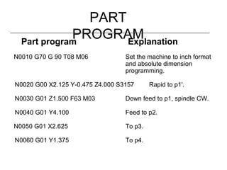
  • 51. PART PROGRAMPart program Explanation N0010 G70 G 90 T08 M06 Set the machine to inch format and absolute dimension programming. N0020 G00 X2.125 Y-0.475 Z4.000 S3157 Rapid to p1'. N0030 G01 Z1.500 F63 M03 Down feed to p1, spindle CW. N0040 G01 Y4.100 Feed to p2. N0050 G01 X2.625 To p3. N0060 G01 Y1.375 To p4.
  • 52. PART PROGRAMPart program Explanation N0070 G01 X3.000 To p5. N0080 G03 Y2.625 I3.000 J2.000 Circular interpolation to p6. N0090 G01 Y2.000 To p7. N0100 G01 X2.625 To p8. N0110 G01 Y-0.100 To p9 N0120 G00 Z4.000 T02 M05 To p9', spindle off, tool #2. N0130 F9.16 S509 M06 Tool change, set new feed and speed. N0140 G81 X0.750 Y1.000 Z-0.1 R2.100 M03 Drill hole 1. N0150 G81 X0.750 Y3.000 Z-0.1 R2.100 Drill hole 2. N0160 G00 X-1.000 Y-1.000 M30 Move to home position, stop the machine.
  • 55. Offset s• Fixture – G10, G54, G54.1 • Diameter • Tool – Length compensation – Part-Edge compensation • Cutter Compensation – Next Slides • Others Discussed in Lab Exercises (Simulators)
  • 56. Tool Radius Compensation• Cutter Compensation Shifting tool path so that the actual finished cut is either moved to the left or right of the programmed path. • Normally, shifted exactly by tool radius • Tool Entry and Exit Issues
  • 57. Tool Radius CompensationStart of Compensation. G41 (or G42) and G01 in the same block ramp takes place at block N0010. N0010 G01 G42 X0.500 Y1.700 N0020 G01 X1.500 G41 (or G42) and G01 in separate blocks the compensation is effective from the start. N0010 G41 N0020 G01 X0.500 Y1.700 N0030 G01 X1.500 (a) G41 (b) G42 G41 G42 G41 G42 (0.5, 1.7) (1.5, 1.7)
  • 58. Tool Radius CompensationInside Corner. Cutter path is inside a corner, stops at the inside cutting point N0010 G41 N0020 G01 X1.500 Y2.000 N0030 G01 X0.000 Y1.600 Use of M96 and M97. Cutting tool that is larger than the height of the step, M97 must be used N0010 G41 N0020 G01 X1.000 Y1.000 N0030 G01 Y0.800 M97 N0040 G01 X2.000 G42 G41 M96 G41 M97 (1.5, 2.0) (0, 1.6)
  • 59. TOOL-RADIUS COMPENSATION Cancel Tool Compensation. G40 in the same block ramp off block. N0060 G40 X2.000 Y1.700 M02 G40 in a block following the last motion, the compensation is effective to the end point (2.000,1.700). N0060 X2.000 Y1.700 N0070 G40 M02 G41 G42 G40 G41 G42 G40 (2.000, 1.700) (2.000, 1.700)
  • 60. EXAMPL EA square 2.0 in. x 2.0 in. is to be milled using a 1/2 in. end milling cutter. Write an NC part program to make the square. Solution Let us set up the lower left corner of the square at (6.0,6.0). Using tool-radius compensation, the square can be produced. 2.000 2.000 (6,6)
  • 61. PART PROGRAMPart Program N0010 G41 S1000 F5 M03 N0020 G00 X6.000 Y6.000 N0030 G01 Z-1.000 N0040 Y8.000 N0050 X8.000 N0060 Y6.000 N0070 X6.000 N0080 Z1.000 N0090 G40 M30 Explanation Begincompensation, set feed and speed, spindle on Move to lower left corner Plunge downthe tool Cut to upper left corner Cut to upper right corner Cut to lower right corner Cut to lower left corner Lift the tool End compensation, stop the machine
  • 62. Exercise • Complete the exercise on setting up an NC machine. The exercise can be found at http://www.engr.psu.edu/cim/ie450/ie450as2.do c
  • 64. TURNIN G IMAGINARY TOOL POINT Programming tool point Surfaces cut No compensation needed. Programmed tool path Surface created
  • 65. COMPUTER ASSISTE PART PROGRAMMING Machine-oriented languages - machine specific General-purpose languages - use post processors to generate machine specific code Translate input symbols Arithmetic calculation Cutter offset calculations Post processing Part program Language Processor N-G code CL data RS-494 CL BCL RS-273 Post Processor
  • 66. Summary • NC can reduce machining skill • NC can reduce the time required to machine a part • NC provides sophisticated contour capability • NC is a flexible method for manufacture of sophisticated machined components

Editor's Notes

  • #2: 1 Questions and Comments: R. A. Wysk, Ph.D. [email_address] Last Modified: 08.24.02 Dr. R. A. Wysk
  • #3: 1 No other notes have been provided in this presentation. The primary reference for this lecture is Chang et al., 1998 - Chapter 9 (required reading). Chapter 10 is dealt with in another presentation.
  • #4: There are several references that can be used here. The web site contains a CNC Machining Center User’s Manual. It is operational at this time.
  • #5: Students should understand what operations should be used to produce what feature. Planning a simple prismatic part is a good warm up activity for students. Here I have used the same exercise that was used for the first Lean Manufacturing Module.
  • #29: 2
  • #30: 3
  • #31: 4
  • #32: 5
  • #33: 6
  • #34: 6
  • #35: Refer to Part 1 of presentation – on types of NC machines, servo mechanisms, etc.
  • #36: 7
  • #37: 7 Discuss a simple example of moving from one point to another, ask for class input
  • #38: 8
  • #39: 7
  • #40: 8
  • #41: 9
  • #42: 10
  • #43: 11 G02 – refers to CW. G01 for CCW. G codes discussed earlier. Ask class for another example
  • #44: 12 Discuss the elements of the example.
  • #45: 13
  • #46: 14
  • #47: 15
  • #48: 16
  • #49: 17
  • #50: 18
  • #51: 19
  • #52: 20
  • #53: 20
  • #54: 21
  • #55: 22
  • #56: 23
  • #57: 23
  • #58: 23
  • #59: 24
  • #60: 25
  • #61: 26
  • #62: 27
  • #64: 28
  • #65: 29