SlideShare a Scribd company logo
Network Essentials Session 1 R. Venkateswaran
Outline Session 1 7-Layer OSI Model Network Layer protocols (Internet Protocol) Transport Layer protocols (TCP and UDP) Session 2 Socket Programming – with focus on  BSD Sockets Sample codes in  C  that work on  UNIX/Linux  systems
Acknowledgments This presentation has been adapted from presentations available at: Prof. Shivkumar Kalyanaraman (http://www.ecse.rpi.edu/Homepages/shivkuma/) Prof. Sneha Kumar Kasera  (http://www.cs.utah.edu/classes/cs5480/) Prof. David Hollinger (http://www.cs.rpi.edu/~hollingd/netprog) South Asian Network Operators Group (http://ws.edu.isoc.org/workshops/2004/SANOG-IV/ip-services/presentations/ip-intro/ipbasics.ppt)
Network Models Formal models allow us to deal with various aspects of networks abstractly One such model is the OSI reference model The OSI reference model is a  layered  model Divide a task into pieces and then solve each piece independently Establishing a well defined interface between layers Major Advantages: Each layer can be implemented independently Adaptability Code Reuse Extensibility
OSI 7-Layer Model IP TCP/UDP Virtual End-to-end connectivity Path selection, Internetworking Error-free communication links Transmission of raw signal Mail, Web, etc. 1 3 2 4 5 6 7 Ethernet Data encryption,compression Managing sessions Funtionality Examples Layers Application Presentation Session Transport Network Data Link Physical
OSI 7-Layer Host Router Router Host End to end Hop by hop Application Presentation Session Transport Network Link Physical Network Link Link Network Link Link Physical Physical Application Presentation Session Transport Network Link
TCP/IP Model Host Router Router End to end No session or presentation layers in TCP/IP model Host Hop by hop Application Transport Network Link Physical Network Link Link Network Link Link Physical Physical Application Transport Network Link
Packet structure Trailer Header Header Header Application Transport Network Data Link Data Transport Layer Data Network Layer Data Link Layer Data
Network Layer
Internet Architecture Packet-switched, connectionless datagram network IP is  the  network layer protocol Acts as a glue  Hourglass concept all hosts and routers run IP Stateless architecture no per flow state inside the network Hop-by-hop packet forwarding Header contains all the information
IP - Minimalist Approach Dumb network Connectivity  is the key Network provides minimal functionalities to support connectivity Addressing, forwarding, routing Smart end systems Transport layer or application performs more sophisticated functionalities Flow control, error control, congestion control Advantages High scalability Works across heterogeneous technologies (Ethernet, modem, satellite, wireless) Supports diverse applications (telnet, ftp, Web, media streaming) Decentralized network administration
IPv4 Header Transport Layer Data… 0 4 8 16 32 IHL Type of Service Total Length Version Fragment Offset Identification Flags Time to Live Protocol Header Checksum Source Address Destination Address Padding Options
IP Address IP address: Unique identification of the end-system from a network-layer perspective IP address is 32-bits long (version 4) Contains a network ID and host ID Use subnet mask to detect the network ID Example of IP address: 133.27.162.125 133 27 162 125 10000101 00011011 10100010 01111101 85 1B A2 7D Decimal Binary HEX NetID Host ID Boundary
Network Mask Define which bits are used to describe the network ID Different Representations: Decimal dot notation: 255.255.224.0 Number of network bits: /19 Bitwise-AND of 32-bit IP address with 32-bit netmask yields network ID part of the address (truncated appropriately)
Network Mask Examples 137.158.128.0/ 17  (netmask  255.255.128.0 ) 1111 1111 1111 1111  1  000 0000  0000 0000  1111 1111 1111 1111  0000 0000  0000 0000  1111 1111 1111 1111  1111 1111 11  00 0000  198.134.0.0/ 16  (netmask  255.255.0.0 ) 205.37.193.128/ 26   (netmask  255.255.255.192 ) 1000 1001  1001 1110  1  000 0000  0000 0000  1100 0110  1000 0110  0000 0000  0000 0000  1100 1101  0010 0101  1100 0001 10  00 0000
Subnets All device interfaces having the  same  network ID are part of the same  subnet Devices within a subnet  can communicate with  each other  without  an intervening router Network consisting of 3 subnets 192.1.1.2 192.1.1.1 192.1.1.3 192.1.1.4 192.1.2.9 192.1.2.2 192.1.2.1 192.1.3.2 192.1.3.1 192.1.3.27
IP router A device with more than one link-layer interface Each interface identified by a different IP address (from different subnets) Packets arriving at one interface are forwarded out on another interface to get them closer to the destination Creates and maintains forwarding tables Tables help in making forwarding decisions Tables created and updated based on routing information exchanged between routers Each router maintains its own forwarding table
Hop by Hop Forwarding
IP Forwarding Rules - I Destination is in the same subnet (direct connectivity) Recognize that destination IP address is on same subnet Find the destination’s datalink-layer address  IP packet encapsulated and sent directly to the destination’s datalink-layer address Destination is in a different subnet (indirect connectivity) Recognize that destination IP address is on different subnet Look up destination IP address in a (L3 forwarding) table to find a match, called the next hop router IP address Find the next hop router’s datalink-layer address IP packet encapsulated and sent directly to the next hop router’s datalink-layer address
IP Forwarding Rules - II Problem 1: Recognize if destination is on the same subnet Use netmask to compute network ID of the destination and match it with device’s network ID Problem 2: Find a device’s datalink-layer address Static mapping  Dynamic mapping using Address Resolution Protocol (ARP) Sender host broadcasts a request: “ What is the Ethernet address of 192.1.1.4? ” The device whose IP address is 192.1.1.4 replies back: “ The Ethernet address for 192.1.1.4 is 00-0C-F1-4E-2A-E2 ” ARP responses are cached at the sender Use  arp  command to view/modify the cache
Look up Forwarding Table Destination =12.5.9.16 ------------------------------- payload  Prefix  Interface  Next Hop  12.0.0.0/8  10.14.22.19  eth1  12.4.0.0/15  12.5.9.0/24  attached  eth2  Serial 1/0/7  10.1.3.77  IP Forwarding Table  0.0.0.0/0  10.14.11.33  eth0  even better OK better best! Longest Prefix Match (Classless) Forwarding
IP Forwarding – Example 1 Forwarding Table on host 192.1.1.1 Note:  127.0.0.1  is the special address of the local interface 192.1.3.2 192.1.1.2 192.1.1.1 192.1.1.3 192.1.1.4 192.1.3.1 192.1.3.27
IP Forwarding – Example 2 Forwarding Table on host 192.1.1.1 Note:  127.0.0.1  is the special address of the local interface 192.1.3.2 192.1.1.2 192.1.1.1 192.1.1.3 192.1.1.4 192.1.3.1 192.1.3.27
IP Forwarding – Example 2 Forwarding Table on host 192.1.1.4 Note:  127.0.0.1  is the special address of the local interface 192.1.3.2 192.1.1.2 192.1.1.1 192.1.1.3 192.1.1.4 192.1.3.1 192.1.3.27
Routing Protocols Distance Vector Routing protocol Each router sends a vector of distances to  its neighbors Vector contains distances to  all  the nodes Each router computes next hop towards different nodes Iterative, Asynchronous, Distributed computation Link State Routing Protocol Each router sends a vector of distances to  all   the nodes Vector contains distances to  only  the neighbors Each router has complete topology information Can compute shortest paths to different nodes
Distance vector algorithm - I Basic idea:   Each node periodically sends its own distance vector estimate to neighbors When a node  x  receives new DV estimate from neighbor, it updates its own DV using Bellman-Ford equation: D x (z) ← min v {c(x,v) + D v (z)}  for each node z  ∊  N Nexthop x  (z) = v Under natural conditions, the estimate  D x (z) converges to the actual least cost  d x (z)
2  0  1 from from x  y  z x y z 0  2  3 from cost to x  y  z x y z 0  2  3 from cost to x  y  z x y z ∞ ∞ ∞ ∞ ∞ cost to x  y  z x y z 0  2  7 from cost to x  y  z x y z 0  2  3 from cost to x  y  z x y z 0  2  3 from cost to x  y  z x y z 0  2  7 from cost to x  y  z x y z ∞ ∞ ∞ 7 1 0 cost to ∞  ∞  ∞ 2  0  1 7  1  0 2  0  1 7  1  0 2  0  1 3  1  0 2  0  1 3  1  0 2  0  1 3  1  0 2  0  1 3  1  0 time node x table node y table node z table D x (y) = min{c(x,y) + D y (y), c(x,z) + D z (y)}    = min{2+0 , 7+1} = 2 D x (z) =  min{ c(x,y) +    D y (z), c(x,z) + D z (z) }  = min{2+1 , 7+0} = 3 ∞ x  y  z x y z 0  2  7 ∞ ∞ ∞ ∞ ∞ ∞ from cost to x z 1 2 7 y
Distance Vector: link cost changes Link cost changes: node detects local link cost change  updates routing info, recalculates  distance vector if DV changes, notify neighbors  “ good news  travels fast” At time  t 0 ,  y  detects the link-cost change, updates its DV,  and informs its neighbors. At time  t 1 ,  z  receives the update from  y  and updates its table.  It computes a new least cost to  x   and sends its neighbors its DV. At time  t 2 ,  y  receives  z ’s update and updates its distance table.  y ’s least costs do not change and hence  y   does  not  send any  message to  z .  x z 1 4 50 y 1
Distance Vector: link cost changes Link cost changes: good news travels fast  bad news travels slow - “count to infinity” problem! 44 iterations before algorithm stabilizes: see text Poisoned reverse:   If Z routes through Y to get to X : Z tells Y its (Z’s) distance to X is infinite (so Y won’t route to X via Z) will this completely solve count to infinity problem?  x z 1 4 50 y 60
Comparison of LS and DV algorithms Message complexity LS:  with n nodes, E links, O(nE) msgs sent  DV:  exchange between neighbors only convergence time varies Speed of Convergence LS:  O(n 2 ) algorithm requires O(nE) msgs may have oscillations DV : convergence time varies may be routing loops count-to-infinity problem Robustness:  what happens if router malfunctions? LS:   node can receive incorrect  link  cost each node computes only its  own  table DV: DV node can advertise incorrect  path  cost each node’s table used by others  error propagate thru network
Transport Layer
Transport Protocols Protocol implemented entirely at the ends Completeness/correctness of function implementations User Datagram Protocol (UDP) provides just integrity and demultiplexing Transmission Control Protocol (TCP) adds… Connection-orientedness (point-to-point) Reliability In-Order delivery Byte-stream Full duplex Flow and congestion control
UDP: User Datagram Protocol  [RFC 768] “ No frills”, “bare bones” Internet transport protocol “ best effort” service, UDP segments may be: lost delivered out of order to the application connectionless: no handshaking between UDP sender, receiver each UDP datagram handled independently of others Why is there a UDP? No connection establishment => Faster communication simple: no connection state at sender, receiver small 8-byte header (lower overheads) no congestion control: UDP can blast away as fast as desired Streaming Multimedia apps, DNS, SNMP benefit from UDP 0 16 32 Source Port Destination Port Length Checksum Application Layer Data…
TCP Header 0 Source Port Destination Port Sequence Number Acknowledgement Number Data Offset Window Reserved ACK URG EOL RST SYN FIN Checksum Urgent Pointer Padding Options 4 8 16 32 Application Layer Data…
Connection:  Three-Way  Handshake TCP connection-establishment: 3-way-handshake necessary and sufficient for unambiguous setup/teardown even under conditions of loss, duplication, and delay
TCP Connection Setup: FSM CLIENT SERVER
TCP – Streams-based Host A Seq=100, 20 bytes data ACK=100 Host B Seq=92, 8 bytes data ACK=120 SendBase = 120 Sendbase = 100 time
TCP is Network-friendly Reliable transmission  Sliding window concept Flow control Regulated by the receiver Congestion Control Regulated by the sender Additive Increase, Multiplicative Decrease Fairness of TCP streams
Stop-and-Wait operation first packet bit transmitted, t = 0 sender receiver RTT   last packet bit transmitted,  t = L / R first packet bit arrives last packet bit arrives, send ACK ACK arrives, send next  packet,  t = RTT + L / R
Pipelining: increased utilization first packet bit transmitted, t = 0 sender receiver RTT  last bit transmitted, t = L / R first packet bit arrives last packet bit arrives, send ACK ACK arrives, send next  packet, t = RTT + L / R last bit of 2 nd  packet arrives, send ACK last bit of 3 rd  packet arrives, send ACK Increase utilization by a factor of 3!
Go-Back-N Sender: k-bit seq # in pkt header “ window” of up to N, consecutive unack’ed pkts allowed ACK(n): ACKs all pkts up to, including seq # n - “cumulative ACK” may receive duplicate ACKs (see receiver) timer for each in-flight pkt timeout(n):  retransmit pkt n and all higher seq # pkts in window
Go-Back-N
TCP Flow Control receive side of TCP connection has a receive buffer: speed-matching service: matching the send rate to the receiving app’s drain rate app process may be slow at reading from buffer sender won’t overflow receiver’s buffer by transmitting too much, too fast flow control
TCP Flow control: how it works (Suppose TCP receiver discards out-of-order segments) spare room in buffer = RcvWindow = RcvBuffer-[LastByteRcvd - LastByteRead] Rcvr advertises spare room by including value of  RcvWindow  in segments Sender limits unACKed data to  RcvWindow guarantees receive buffer doesn’t overflow
TCP congestion control: two “phases” slow start congestion avoidance important variables: Congwin threshold:  defines threshold between two slow start phase, congestion control phase “ probing”  for usable bandwidth:   ideally:  transmit as fast as possible ( Congwin  as large as possible) without loss increase   Congwin  until loss (congestion) loss:  decrease   Congwin , then begin probing (increasing) again
TCP Slowstart exponential increase (per RTT) in window size (not so slow!) loss event: timeout (Tahoe TCP)  initialize: Congwin = 1 for (each segment ACKed) Congwin++ until (loss event OR CongWin > threshold) Host A one segment RTT Host B two segments four segments Slowstart algorithm time
TCP Congestion Avoidance: Tahoe /* slowstart is over  */  /* Congwin > threshold */ Until (loss event) { every w segments ACKed: Congwin++ } threshold = Congwin/2 Congwin = 1 perform slowstart TCP Tahoe Congestion avoidance
Where to from here? IP designed for best-effort service only Affecting new applications like media streaming, VoIP Should the network become application-aware? Should the IP routers look beyond the IP header? We are already running short of IP addresses Solution:  IPv6  – yet to become widespread Temporary fix:  Network Address Translation  (NAT) TCP or UDP may not be the best suited for reliable media streaming Answer:  Stream Control Transmission Protocol (SCTP) SCTP combines the datagram orientation of UDP with the sequencing and reliability of TCP SCTP uses multi-streaming, message-oriented routing
Outline Session 1 7-Layer OSI Model Network Layer protocols (Internet Protocol) Transport Layer protocols (TCP and UDP) Session 2 Socket Programming – with focus on  BSD Sockets Sample codes in  C  that work on  UNIX/Linux  systems
Thank You !
BACKUP
TCP retransmission - I Premature Timeout Host A Seq=100, 20 bytes data ACK=100 time Host B Seq=92, 8 bytes data ACK=120 Seq=92, 8 bytes data Seq=92 timeout ACK=120 Seq=92 timeout SendBase = 120 SendBase = 120 Sendbase = 100
TCP retransmission - II Lost ACK packet Host A Seq=92, 8 bytes data ACK=100 loss timeout Host B X Seq=92, 8 bytes data ACK=100 time SendBase = 100
TCP Connection Tear-down Sender Receiver FIN FIN-ACK FIN FIN-ACK Data write Data ack
TCP Connection Tear-down: FSM CLOSING CLOSE WAIT FIN WAIT-1 ESTAB TIME WAIT snd FIN CLOSE send FIN CLOSE rcv ACK of FIN LAST-ACK CLOSED FIN WAIT-2 snd ACK rcv FIN delete TCB Timeout=2msl send FIN CLOSE send ACK rcv FIN snd ACK rcv FIN rcv ACK of FIN snd ACK rcv FIN+ACK
TCP retransmission - III Cumulative ACKs Host A Seq=92, 8 bytes data ACK=100 loss timeout Host B X Seq=100, 20 bytes data ACK=120 time SendBase = 120
Selective Ack
Selective Ack - Example
Ad

Recommended

Week11 lec2
Week11 lec2
syedhaiderraza
 
Intro tcp-ip
Intro tcp-ip
Zoulou Adams
 
Week13 lec2
Week13 lec2
syedhaiderraza
 
Week13 lec1
Week13 lec1
syedhaiderraza
 
Week16 lec1
Week16 lec1
syedhaiderraza
 
Week15 lec1
Week15 lec1
syedhaiderraza
 
Ec8551 communication networks mcq question bank
JAIGANESH SEKAR
 
Ch22
Ch22
Balaji Prasath Madhaiyan
 
Computer network
Computer network
Gaurav Rawat
 
Networking basics and basic cisco commands
Krishna Mohan
 
Aspects Stratégiques des Réseaux
Eric Vyncke
 
Switching units
Switching units
Syed Zaid Irshad
 
Network Layer
Network Layer
Kamal Acharya
 
Expt no.3
Expt no.3
rahul kbp
 
Question bank cn2
Question bank cn2
sangusajjan
 
Chapter 5 : Link Layer
Amin Omi
 
Computer Networks Homework Help
Assignmentpedia
 
Prb#5
Prb#5
Ahmad Osama
 
02 Network Models
02 Network Models
Ahmar Hashmi
 
20CS2008 Computer Networks
Kathirvel Ayyaswamy
 
Lecture 06
Lecture 06
Naveen Shivegowda
 
Concept of Network Routing Layer
Pawan Singh
 
Basic Networking
Basic Networking
CEC Landran
 
Data and computer communication exam i
Andrew Ibrahim
 
20CS2007 Computer Communication Networks
Kathirvel Ayyaswamy
 
CS6601 DISTRIBUTED SYSTEMS
Kathirvel Ayyaswamy
 
Vlsm
Vlsm
Computer Hardware & Trouble shooting
 
Datalinklayer tanenbaum
Mahesh Kumar Chelimilla
 
Study Are B2 B Companies Getting It
Nicolas Jambin
 
Honduras Powerpoint
Honduras Powerpoint
getitgotitgurr
 

More Related Content

What's hot (20)

Computer network
Computer network
Gaurav Rawat
 
Networking basics and basic cisco commands
Krishna Mohan
 
Aspects Stratégiques des Réseaux
Eric Vyncke
 
Switching units
Switching units
Syed Zaid Irshad
 
Network Layer
Network Layer
Kamal Acharya
 
Expt no.3
Expt no.3
rahul kbp
 
Question bank cn2
Question bank cn2
sangusajjan
 
Chapter 5 : Link Layer
Amin Omi
 
Computer Networks Homework Help
Assignmentpedia
 
Prb#5
Prb#5
Ahmad Osama
 
02 Network Models
02 Network Models
Ahmar Hashmi
 
20CS2008 Computer Networks
Kathirvel Ayyaswamy
 
Lecture 06
Lecture 06
Naveen Shivegowda
 
Concept of Network Routing Layer
Pawan Singh
 
Basic Networking
Basic Networking
CEC Landran
 
Data and computer communication exam i
Andrew Ibrahim
 
20CS2007 Computer Communication Networks
Kathirvel Ayyaswamy
 
CS6601 DISTRIBUTED SYSTEMS
Kathirvel Ayyaswamy
 
Vlsm
Vlsm
Computer Hardware & Trouble shooting
 
Datalinklayer tanenbaum
Mahesh Kumar Chelimilla
 

Viewers also liked (6)

Study Are B2 B Companies Getting It
Nicolas Jambin
 
Honduras Powerpoint
Honduras Powerpoint
getitgotitgurr
 
Munier BBN Digital
Munier BBN Digital
Nicolas Jambin
 
The Collective
The Collective
Michael van den Heerik
 
Pres Digital Uk 210709
Nicolas Jambin
 
Workflow Xs
Workflow Xs
Michael van den Heerik
 
Ad

Similar to Intro 2 Computer Networks (20)

module10-rip (1).ppt
Rakesh Dhiman
 
09 module determinig ip routes
Asif
 
Routing.pptbbbbbbbbbbbbbbbbbbbbbnbbnbbbbnbb
nijjilnarula1
 
destination. The network layer must know the topology of the subnet and choos...
Ashish Gupta
 
Network_Layer.ppt
Network_Layer.ppt
RajSingh52036
 
Day 8 1 introducing routing n
CYBERINTELLIGENTS
 
computer communications
JAYASHSINGHRA2111003
 
Group 1
Group 1
lifetobeart
 
Part7-routing.pptx
Part7-routing.pptx
Olivier Bonaventure
 
NETWORK LAYER.ppt
NETWORK LAYER.ppt
DrTThendralCompSci
 
Networking.ppt
Networking.ppt
MayurJagtap53
 
Routing in Engineering: Principles and Applications.ppt
Bchakri3
 
NetworkAlgorithms.ppt
21121A0594
 
Routing
Routing
Amit Pandey
 
Network Layer
Network Layer
reshmadayma
 
routing
routing
tumetr1
 
Cs8591 Computer Networks
Kathirvel Ayyaswamy
 
Powerpoint one
Powerpoint one
pqatester
 
Powerpoint one
Powerpoint one
pqatester
 
Routing Protocols
Routing Protocols
Dr.Ashvini Chaudhari Bhongade
 
module10-rip (1).ppt
Rakesh Dhiman
 
09 module determinig ip routes
Asif
 
Routing.pptbbbbbbbbbbbbbbbbbbbbbnbbnbbbbnbb
nijjilnarula1
 
destination. The network layer must know the topology of the subnet and choos...
Ashish Gupta
 
Day 8 1 introducing routing n
CYBERINTELLIGENTS
 
Routing in Engineering: Principles and Applications.ppt
Bchakri3
 
NetworkAlgorithms.ppt
21121A0594
 
Powerpoint one
Powerpoint one
pqatester
 
Powerpoint one
Powerpoint one
pqatester
 
Ad

Intro 2 Computer Networks

  • 1. Network Essentials Session 1 R. Venkateswaran
  • 2. Outline Session 1 7-Layer OSI Model Network Layer protocols (Internet Protocol) Transport Layer protocols (TCP and UDP) Session 2 Socket Programming – with focus on BSD Sockets Sample codes in C that work on UNIX/Linux systems
  • 3. Acknowledgments This presentation has been adapted from presentations available at: Prof. Shivkumar Kalyanaraman (http://www.ecse.rpi.edu/Homepages/shivkuma/) Prof. Sneha Kumar Kasera (http://www.cs.utah.edu/classes/cs5480/) Prof. David Hollinger (http://www.cs.rpi.edu/~hollingd/netprog) South Asian Network Operators Group (http://ws.edu.isoc.org/workshops/2004/SANOG-IV/ip-services/presentations/ip-intro/ipbasics.ppt)
  • 4. Network Models Formal models allow us to deal with various aspects of networks abstractly One such model is the OSI reference model The OSI reference model is a layered model Divide a task into pieces and then solve each piece independently Establishing a well defined interface between layers Major Advantages: Each layer can be implemented independently Adaptability Code Reuse Extensibility
  • 5. OSI 7-Layer Model IP TCP/UDP Virtual End-to-end connectivity Path selection, Internetworking Error-free communication links Transmission of raw signal Mail, Web, etc. 1 3 2 4 5 6 7 Ethernet Data encryption,compression Managing sessions Funtionality Examples Layers Application Presentation Session Transport Network Data Link Physical
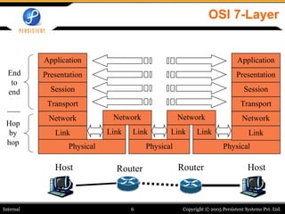
  • 6. OSI 7-Layer Host Router Router Host End to end Hop by hop Application Presentation Session Transport Network Link Physical Network Link Link Network Link Link Physical Physical Application Presentation Session Transport Network Link
  • 7. TCP/IP Model Host Router Router End to end No session or presentation layers in TCP/IP model Host Hop by hop Application Transport Network Link Physical Network Link Link Network Link Link Physical Physical Application Transport Network Link
  • 8. Packet structure Trailer Header Header Header Application Transport Network Data Link Data Transport Layer Data Network Layer Data Link Layer Data
  • 10. Internet Architecture Packet-switched, connectionless datagram network IP is the network layer protocol Acts as a glue Hourglass concept all hosts and routers run IP Stateless architecture no per flow state inside the network Hop-by-hop packet forwarding Header contains all the information
  • 11. IP - Minimalist Approach Dumb network Connectivity is the key Network provides minimal functionalities to support connectivity Addressing, forwarding, routing Smart end systems Transport layer or application performs more sophisticated functionalities Flow control, error control, congestion control Advantages High scalability Works across heterogeneous technologies (Ethernet, modem, satellite, wireless) Supports diverse applications (telnet, ftp, Web, media streaming) Decentralized network administration
  • 12. IPv4 Header Transport Layer Data… 0 4 8 16 32 IHL Type of Service Total Length Version Fragment Offset Identification Flags Time to Live Protocol Header Checksum Source Address Destination Address Padding Options
  • 13. IP Address IP address: Unique identification of the end-system from a network-layer perspective IP address is 32-bits long (version 4) Contains a network ID and host ID Use subnet mask to detect the network ID Example of IP address: 133.27.162.125 133 27 162 125 10000101 00011011 10100010 01111101 85 1B A2 7D Decimal Binary HEX NetID Host ID Boundary
  • 14. Network Mask Define which bits are used to describe the network ID Different Representations: Decimal dot notation: 255.255.224.0 Number of network bits: /19 Bitwise-AND of 32-bit IP address with 32-bit netmask yields network ID part of the address (truncated appropriately)
  • 15. Network Mask Examples 137.158.128.0/ 17 (netmask 255.255.128.0 ) 1111 1111 1111 1111 1 000 0000 0000 0000 1111 1111 1111 1111 0000 0000 0000 0000 1111 1111 1111 1111 1111 1111 11 00 0000 198.134.0.0/ 16 (netmask 255.255.0.0 ) 205.37.193.128/ 26 (netmask 255.255.255.192 ) 1000 1001 1001 1110 1 000 0000 0000 0000 1100 0110 1000 0110 0000 0000 0000 0000 1100 1101 0010 0101 1100 0001 10 00 0000
  • 16. Subnets All device interfaces having the same network ID are part of the same subnet Devices within a subnet can communicate with each other without an intervening router Network consisting of 3 subnets 192.1.1.2 192.1.1.1 192.1.1.3 192.1.1.4 192.1.2.9 192.1.2.2 192.1.2.1 192.1.3.2 192.1.3.1 192.1.3.27
  • 17. IP router A device with more than one link-layer interface Each interface identified by a different IP address (from different subnets) Packets arriving at one interface are forwarded out on another interface to get them closer to the destination Creates and maintains forwarding tables Tables help in making forwarding decisions Tables created and updated based on routing information exchanged between routers Each router maintains its own forwarding table
  • 18. Hop by Hop Forwarding
  • 19. IP Forwarding Rules - I Destination is in the same subnet (direct connectivity) Recognize that destination IP address is on same subnet Find the destination’s datalink-layer address IP packet encapsulated and sent directly to the destination’s datalink-layer address Destination is in a different subnet (indirect connectivity) Recognize that destination IP address is on different subnet Look up destination IP address in a (L3 forwarding) table to find a match, called the next hop router IP address Find the next hop router’s datalink-layer address IP packet encapsulated and sent directly to the next hop router’s datalink-layer address
  • 20. IP Forwarding Rules - II Problem 1: Recognize if destination is on the same subnet Use netmask to compute network ID of the destination and match it with device’s network ID Problem 2: Find a device’s datalink-layer address Static mapping Dynamic mapping using Address Resolution Protocol (ARP) Sender host broadcasts a request: “ What is the Ethernet address of 192.1.1.4? ” The device whose IP address is 192.1.1.4 replies back: “ The Ethernet address for 192.1.1.4 is 00-0C-F1-4E-2A-E2 ” ARP responses are cached at the sender Use arp command to view/modify the cache
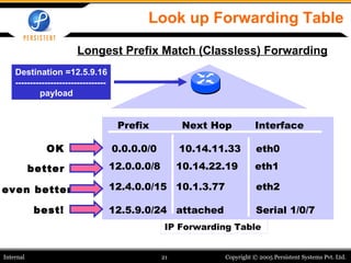
  • 21. Look up Forwarding Table Destination =12.5.9.16 ------------------------------- payload Prefix Interface Next Hop 12.0.0.0/8 10.14.22.19 eth1 12.4.0.0/15 12.5.9.0/24 attached eth2 Serial 1/0/7 10.1.3.77 IP Forwarding Table 0.0.0.0/0 10.14.11.33 eth0 even better OK better best! Longest Prefix Match (Classless) Forwarding
  • 22. IP Forwarding – Example 1 Forwarding Table on host 192.1.1.1 Note: 127.0.0.1 is the special address of the local interface 192.1.3.2 192.1.1.2 192.1.1.1 192.1.1.3 192.1.1.4 192.1.3.1 192.1.3.27
  • 23. IP Forwarding – Example 2 Forwarding Table on host 192.1.1.1 Note: 127.0.0.1 is the special address of the local interface 192.1.3.2 192.1.1.2 192.1.1.1 192.1.1.3 192.1.1.4 192.1.3.1 192.1.3.27
  • 24. IP Forwarding – Example 2 Forwarding Table on host 192.1.1.4 Note: 127.0.0.1 is the special address of the local interface 192.1.3.2 192.1.1.2 192.1.1.1 192.1.1.3 192.1.1.4 192.1.3.1 192.1.3.27
  • 25. Routing Protocols Distance Vector Routing protocol Each router sends a vector of distances to its neighbors Vector contains distances to all the nodes Each router computes next hop towards different nodes Iterative, Asynchronous, Distributed computation Link State Routing Protocol Each router sends a vector of distances to all the nodes Vector contains distances to only the neighbors Each router has complete topology information Can compute shortest paths to different nodes
  • 26. Distance vector algorithm - I Basic idea: Each node periodically sends its own distance vector estimate to neighbors When a node x receives new DV estimate from neighbor, it updates its own DV using Bellman-Ford equation: D x (z) ← min v {c(x,v) + D v (z)} for each node z ∊ N Nexthop x (z) = v Under natural conditions, the estimate D x (z) converges to the actual least cost d x (z)
  • 27. 2 0 1 from from x y z x y z 0 2 3 from cost to x y z x y z 0 2 3 from cost to x y z x y z ∞ ∞ ∞ ∞ ∞ cost to x y z x y z 0 2 7 from cost to x y z x y z 0 2 3 from cost to x y z x y z 0 2 3 from cost to x y z x y z 0 2 7 from cost to x y z x y z ∞ ∞ ∞ 7 1 0 cost to ∞ ∞ ∞ 2 0 1 7 1 0 2 0 1 7 1 0 2 0 1 3 1 0 2 0 1 3 1 0 2 0 1 3 1 0 2 0 1 3 1 0 time node x table node y table node z table D x (y) = min{c(x,y) + D y (y), c(x,z) + D z (y)} = min{2+0 , 7+1} = 2 D x (z) = min{ c(x,y) + D y (z), c(x,z) + D z (z) } = min{2+1 , 7+0} = 3 ∞ x y z x y z 0 2 7 ∞ ∞ ∞ ∞ ∞ ∞ from cost to x z 1 2 7 y
  • 28. Distance Vector: link cost changes Link cost changes: node detects local link cost change updates routing info, recalculates distance vector if DV changes, notify neighbors “ good news travels fast” At time t 0 , y detects the link-cost change, updates its DV, and informs its neighbors. At time t 1 , z receives the update from y and updates its table. It computes a new least cost to x and sends its neighbors its DV. At time t 2 , y receives z ’s update and updates its distance table. y ’s least costs do not change and hence y does not send any message to z . x z 1 4 50 y 1
  • 29. Distance Vector: link cost changes Link cost changes: good news travels fast bad news travels slow - “count to infinity” problem! 44 iterations before algorithm stabilizes: see text Poisoned reverse: If Z routes through Y to get to X : Z tells Y its (Z’s) distance to X is infinite (so Y won’t route to X via Z) will this completely solve count to infinity problem? x z 1 4 50 y 60
  • 30. Comparison of LS and DV algorithms Message complexity LS: with n nodes, E links, O(nE) msgs sent DV: exchange between neighbors only convergence time varies Speed of Convergence LS: O(n 2 ) algorithm requires O(nE) msgs may have oscillations DV : convergence time varies may be routing loops count-to-infinity problem Robustness: what happens if router malfunctions? LS: node can receive incorrect link cost each node computes only its own table DV: DV node can advertise incorrect path cost each node’s table used by others error propagate thru network
  • 32. Transport Protocols Protocol implemented entirely at the ends Completeness/correctness of function implementations User Datagram Protocol (UDP) provides just integrity and demultiplexing Transmission Control Protocol (TCP) adds… Connection-orientedness (point-to-point) Reliability In-Order delivery Byte-stream Full duplex Flow and congestion control
  • 33. UDP: User Datagram Protocol [RFC 768] “ No frills”, “bare bones” Internet transport protocol “ best effort” service, UDP segments may be: lost delivered out of order to the application connectionless: no handshaking between UDP sender, receiver each UDP datagram handled independently of others Why is there a UDP? No connection establishment => Faster communication simple: no connection state at sender, receiver small 8-byte header (lower overheads) no congestion control: UDP can blast away as fast as desired Streaming Multimedia apps, DNS, SNMP benefit from UDP 0 16 32 Source Port Destination Port Length Checksum Application Layer Data…
  • 34. TCP Header 0 Source Port Destination Port Sequence Number Acknowledgement Number Data Offset Window Reserved ACK URG EOL RST SYN FIN Checksum Urgent Pointer Padding Options 4 8 16 32 Application Layer Data…
  • 35. Connection: Three-Way Handshake TCP connection-establishment: 3-way-handshake necessary and sufficient for unambiguous setup/teardown even under conditions of loss, duplication, and delay
  • 36. TCP Connection Setup: FSM CLIENT SERVER
  • 37. TCP – Streams-based Host A Seq=100, 20 bytes data ACK=100 Host B Seq=92, 8 bytes data ACK=120 SendBase = 120 Sendbase = 100 time
  • 38. TCP is Network-friendly Reliable transmission Sliding window concept Flow control Regulated by the receiver Congestion Control Regulated by the sender Additive Increase, Multiplicative Decrease Fairness of TCP streams
  • 39. Stop-and-Wait operation first packet bit transmitted, t = 0 sender receiver RTT last packet bit transmitted, t = L / R first packet bit arrives last packet bit arrives, send ACK ACK arrives, send next packet, t = RTT + L / R
  • 40. Pipelining: increased utilization first packet bit transmitted, t = 0 sender receiver RTT last bit transmitted, t = L / R first packet bit arrives last packet bit arrives, send ACK ACK arrives, send next packet, t = RTT + L / R last bit of 2 nd packet arrives, send ACK last bit of 3 rd packet arrives, send ACK Increase utilization by a factor of 3!
  • 41. Go-Back-N Sender: k-bit seq # in pkt header “ window” of up to N, consecutive unack’ed pkts allowed ACK(n): ACKs all pkts up to, including seq # n - “cumulative ACK” may receive duplicate ACKs (see receiver) timer for each in-flight pkt timeout(n): retransmit pkt n and all higher seq # pkts in window
  • 43. TCP Flow Control receive side of TCP connection has a receive buffer: speed-matching service: matching the send rate to the receiving app’s drain rate app process may be slow at reading from buffer sender won’t overflow receiver’s buffer by transmitting too much, too fast flow control
  • 44. TCP Flow control: how it works (Suppose TCP receiver discards out-of-order segments) spare room in buffer = RcvWindow = RcvBuffer-[LastByteRcvd - LastByteRead] Rcvr advertises spare room by including value of RcvWindow in segments Sender limits unACKed data to RcvWindow guarantees receive buffer doesn’t overflow
  • 45. TCP congestion control: two “phases” slow start congestion avoidance important variables: Congwin threshold: defines threshold between two slow start phase, congestion control phase “ probing” for usable bandwidth: ideally: transmit as fast as possible ( Congwin as large as possible) without loss increase Congwin until loss (congestion) loss: decrease Congwin , then begin probing (increasing) again
  • 46. TCP Slowstart exponential increase (per RTT) in window size (not so slow!) loss event: timeout (Tahoe TCP) initialize: Congwin = 1 for (each segment ACKed) Congwin++ until (loss event OR CongWin > threshold) Host A one segment RTT Host B two segments four segments Slowstart algorithm time
  • 47. TCP Congestion Avoidance: Tahoe /* slowstart is over */ /* Congwin > threshold */ Until (loss event) { every w segments ACKed: Congwin++ } threshold = Congwin/2 Congwin = 1 perform slowstart TCP Tahoe Congestion avoidance
  • 48. Where to from here? IP designed for best-effort service only Affecting new applications like media streaming, VoIP Should the network become application-aware? Should the IP routers look beyond the IP header? We are already running short of IP addresses Solution: IPv6 – yet to become widespread Temporary fix: Network Address Translation (NAT) TCP or UDP may not be the best suited for reliable media streaming Answer: Stream Control Transmission Protocol (SCTP) SCTP combines the datagram orientation of UDP with the sequencing and reliability of TCP SCTP uses multi-streaming, message-oriented routing
  • 49. Outline Session 1 7-Layer OSI Model Network Layer protocols (Internet Protocol) Transport Layer protocols (TCP and UDP) Session 2 Socket Programming – with focus on BSD Sockets Sample codes in C that work on UNIX/Linux systems
  • 52. TCP retransmission - I Premature Timeout Host A Seq=100, 20 bytes data ACK=100 time Host B Seq=92, 8 bytes data ACK=120 Seq=92, 8 bytes data Seq=92 timeout ACK=120 Seq=92 timeout SendBase = 120 SendBase = 120 Sendbase = 100
  • 53. TCP retransmission - II Lost ACK packet Host A Seq=92, 8 bytes data ACK=100 loss timeout Host B X Seq=92, 8 bytes data ACK=100 time SendBase = 100
  • 54. TCP Connection Tear-down Sender Receiver FIN FIN-ACK FIN FIN-ACK Data write Data ack
  • 55. TCP Connection Tear-down: FSM CLOSING CLOSE WAIT FIN WAIT-1 ESTAB TIME WAIT snd FIN CLOSE send FIN CLOSE rcv ACK of FIN LAST-ACK CLOSED FIN WAIT-2 snd ACK rcv FIN delete TCB Timeout=2msl send FIN CLOSE send ACK rcv FIN snd ACK rcv FIN rcv ACK of FIN snd ACK rcv FIN+ACK
  • 56. TCP retransmission - III Cumulative ACKs Host A Seq=92, 8 bytes data ACK=100 loss timeout Host B X Seq=100, 20 bytes data ACK=120 time SendBase = 120
  • 58. Selective Ack - Example