SlideShare a Scribd company logo
ARDUINO EMBEDDED
SYSTEMS AND ADVANCED
ROBOTICS
A Project Report for the Award of the Degree of B.Tech
In
Electronics and Instrumentation Engineering
At
ACADEMY OF TECHNOLOGY
By
Anirvan Misra Roll: 16900513005
Nilesh Tripathi Roll: 16900513022
Shubham Bhattacharya Roll: 16900513043
Siddhartha Mishra Roll: 16900513044
Training Provided by
Tech Learning Solutions pvt. Ltd.
Technical Support given by
Skubotics
In Association with
MYWBUT (www.mywbut.com)
ACKNOWLEDGEMENT
We take this opportunity to express our deep gratitude
and sincerest thank to our project mentor, Tunir Saha
for giving most valuable solution helpful guidance and
encouragement in the execution of this project work.
We will like to give a special mention to our colleagues.
Last but not the least to all the faculty member of Tech
learning solution pvt. Ltd. for the support.
CONTENTS
ACKNOWLEDGEMENT
INTRODUCTION
 Introduction to Embedded Systems
 Introduction to Arduino
 Anatomy of Arduino UNO
 ATmega-328p
 Arduino IDE
INTERFACING WITH ARDUINO UNO
 Interfacing LED
 Interfacing IR Sensors
 Interfacing LDR Sensors
 Interfacing Temperature Sensor
 Interfacing a DC Motor
AUTONOMOUS ROBOTICS USING ARDUINO
 Introduction to Autonomous Robotics
 Line Follower Robot
o Circuit Explanation
o Working Principle
o Code
o Project Snapshot
CONCLUSION
INTRODUCTION
Introduction to Embedded System:
An embedded system is a computer system with a dedicated function within a larger mechanical or
electrical system, often with real-time computing constraints. It is embedded as part of a complete
device often including hardware and mechanical parts. Embedded systems control many devices in
commonuse today. Ninety-eightpercentof all microprocessors are manufacturedascomponentsof
embedded systems.
Embedded systems range from portable devices such as digital watches and MP3 players, to large
stationary installations like traffic lights,factory controllers, and largely complex systems like hybrid
vehicles, MRI, and avionics. Complexity varies from low, with a single microcontroller chip, to very
high with multiple units, peripherals and networks mounted inside a large chassis or enclosure.
The usesof embeddedsystems are virtuallylimitless,becauseeverydaynew productsare introduced
to the market that utilize embedded computers in novel ways.
In recent years, hardware such as microprocessors, microcontrollers, and FPGA chips have become
much cheaper.
Some examples of embedded systemsinclude ATMs, cell phones, printers, thermostats, calculators,
and videogame consoles. Handheld computers or PDAs are also considered embedded devices
because of the nature of their hardware design,eventhough theyare more expandable in software
terms.
Introduction to Arduino:
Arduino is a computer hardware and software company, project, and user community that designs and
manufactures microcontroller kits for building digital devices and interactive objects that can sense and
control objects in the physical world. The project's products are distributed as open-source
hardware and software, which arelicensed under the GNULesser GeneralPublic License (LGPL) or the GNU
General Public License (GPL), permitting the manufacture of Arduino boards and software distribution by
anyone. Arduino boards are available commercially in preassembled form, or as do-it-yourself kits.
Anatomy of Arduino UNO:
Arduino Unois a microcontrollerboardbasedonthe ATmega328P.It has14 digital input/outputpins
(of which6 can be usedasPWMoutputs),6analoginputs,a16 MHz quartz crystal,a USB connection,
a power jack, an ICSP header and a reset button.
It containseverythingneededtosupportthe microcontroller;simplyconnectitto a computerwitha
USB cable or power it with an AC-to-DC adapter or battery to get started.
ATmega328p:
The Atmega328p is a very popular microcontroller chip produced by Atmel. It is an 8-bit
microcontroller that has 32K of flash memory, 1K of EEPROM, and 2K of internal SRAM.
The Atmega328 is one of the microcontroller chips that are used with the popular Arduino
Duemilanoveboards.The ArduinoDuemilanove boardcomeswitheither1of 2 microcontrollerchips,
the Atmega168 or the Atmega328. Of these 2, the Atmega328 is the upgraded,more advancedchip.
Unlike the Atmega168 whichhas 16K of flashprogram memoryand 512 bytesof internal SRAM,the
Atmega328 has 32K of flash program memory and 2K of Internal SRAM.
The Atmega328 has 28 pins.
It has 14 digital I/Opins,of which 6 can be usedas PWM outputsand 6 analog inputpins.These I/O
pins account for 20 of the pins.
Pin configuration
Arduino IDE:
The open-source ArduinoSoftware (IDE)makesiteasytowrite codeanduploadittothe board.Itruns
on Windows, Mac OS X, and Linux.
The environment is written in Java and based on Processing and other open-source software. This
software can be used with any Arduino board. Programs written using Arduino Software (IDE) are
called sketches. These sketches are written in the text editor and are saved with the file extension
.ino. The editor has features for cutting/pasting and for searching/replacing text. First, the Arduino
compiler/IDE accepts C and C++ as-is. In fact many of the libraries are written in C++. Much of the
underlyingsystem is not object oriented, but it could be. Thus, "The arduino language" is C++ or C.
INTERFACING WITH ARDUINO UNO
LED interfacing with Arduino:
To light an external LED, we to build this circuit, where we connect one end of the resistor to the digital pin
correspondent to the LED_BUILTIN constant. Connect the long leg of the LED (the positive leg, called the
anode) to the other end of the resistor. Connect the short leg of the LED (the negative leg, called the
cathode) to the GND. In the diagram below we show an UNO board that has D13 as the LED_BUILTIN
value.The value of the resistor in series with the LED may be of a different value than 220 ohm; the LED will
lit up also with values up to 1K ohm.
Schematic:
Code:
// the setup function runs once when you press reset or power the board
void setup() {
// initialize digital pin LED_BUILTIN as an output.
pinMode(LED_BUILTIN, OUTPUT);
}
// the loop function runs over and over again forever
void loop() {
digitalWrite(LED_BUILTIN, HIGH); // turn the LED on (HIGH is the voltage level)
delay(1000); // wait for a second
digitalWrite(LED_BUILTIN, LOW); // turn the LED off by making the voltage LOW
delay(1000); // wait for a second
}
Interfacing Infrared sensor:
Principle of working
The principle of an IR sensor working as an Object Detection Sensor can be explained using the
followingfigure.AnIRsensorconsistsof an IR LED and an IR Photodiode;togethertheyare calledas
Photo – Coupler or Opto – Coupler.
Whenthe IR transmitteremitsradiation,itreachesthe objectandsome of the radiationreflectsback
to the IR receiver.Basedonthe intensityof the receptionbythe IRreceiver,the outputof the sensor
is defined.Itconsistsof an IR LED, a photodiode,apotentiometer,anIC Operational amplifierandan
LED.IR LED emitsinfraredlight.The Photodiode detectsthe infraredlight.AnICOp – Ampisusedas a
voltage comparator.The potentiometerisusedtocalibrate the outputof the sensoraccordingto the
requirement.When the light emitted by the IR LED is incident on the photodiode after hitting an
object, the resistance of the photodiode fallsdown from a huge value. One of the input of the op –
amp is at threshold value set by the potentiometer. The other input to the op-amp is from the
photodiode’sseriesresistor.Whentheincidentradiationismore onthe photodiode,the voltagedrop
across the seriesresistorwillbe high.Inthe IC,both the thresholdvoltage andthe voltage acrossthe
series resistor are compared. If the voltage across the resistor series to photodiode is greater than
that of the threshold voltage, the output of the IC Op – Amp is high. As the output of the IC is
connected to an LED, it lightens up. The threshold voltage can be adjusted by adjusting the
potentiometer depending on the environmental conditions.
It is universal that black color absorbs the entire radiationincident on it and white color reflects the
entire radiationincidentonit.Basedonthisprinciple,the secondpositioningof the sensorcouplecan
be made. The IR LED and the photodiode are placed side by side. When the IR transmitter emits
infrared radiation, since there is no direct line of contact between the transmitter and receiver, the
emitted radiation must reflect back to the photodiode after hitting any object.
The surface of the objectcan be dividedintotwotypes:reflective surface andnon-reflective surface.
If the surface of the objectisreflectiveinnaturei.e.itiswhite orotherlightcolor,mostof theradiation
incident on it will get reflected back and reaches the photodiode.Depending on the intensity of the
radiation reflected back, current flows in the photodiode.
If the surface of the object is non-reflective in nature i.e. it is black or other dark color, it absorbs
almostall the radiationincidentonit.Asthere isno reflectedradiation,there isnoradiationincident
on the photodiode andthe resistance of the photodiode remainshigherallowingnocurrentto flow.
This situation is similar to there being no object at all.
Schematic:
Code:
//define pins
#define irLedPin 4 // IR Led on this pin
#define irSensorPin 5 // IR sensor on this pin
int irRead(int readPin, int triggerPin); //function prototype
void setup()
{
pinMode(irSensorPin, INPUT);
pinMode(irLedPin, OUTPUT);
Serial.begin(9600);
// prints title with ending line break
Serial.println("Program Starting");
// wait for the long string to be sent
delay(100);
}
void loop()
{
Serial.println(irRead(irSensorPin, irLedPin)); //display the results
delay(10); //wait for the string to be sent
}
Interfacing Light Detecting Resistor:
A Light DependentResistor(LDR) or a photoresistoris a device whose resistivityisa functionof the
incident electromagnetic radiation. Hence, they are light sensitive devices.
Theyare alsocalledasphoto conductors,photoconductive cells orsimplyphotocells.Theyare made
up of semiconductor materials having high resistance.
Schematic:
Code:
int sensorPin = A0; // select the input pin for ldr
int sensorValue = 0; // variable to store the value coming from the sensor
void setup() {
Serial.begin(9600); //sets serial port for communication
}
void loop() {
sensorValue = analogRead(sensorPin); // read the value from the sensor
Serial.println(sensorValue); //prints the values coming from the sensor on the screen
delay(100);
}
Interfacing Temperature Sensor:
Temperature sensor is a device which senses variations in temperature across it. LM35 is a basic
temperature sensor that can be used for experimental purpose. It give the readings in centigrade
(degree Celsius) since its output voltage is linearly proportional to temperature.
Schematic:
Code:
float tempC;
int tempPin = 0;
void setup()
{
Serial.begin(9600); //opens serial port, sets data rate to 9600 bps
}
void loop()
{
tempC = analogRead(tempPin); //read the value from the sensor
tempC = (5.0 * tempC * 100.0)/1024.0; //convert the analog data to temperature
Serial.print((byte)tempC); //send the data to the computer
delay(1000); //wait one second before sending new data
}
Interfacing DC motor:
There are three input pins for each motor, Input1 (IN1),Input2 (IN2), and Enable1 (EN1) for Motor1
and Input3, Input4, and Enable2 for Motor2.
Since we will be controllingonly one motor in this example,we will connect the Arduino to IN1 (pin
5), IN2 (pin7), andEnable1(pin6) of the L298 IC. Pins5 and 7 are digital,i.e.ON orOFF inputs,while
pin 6 needs a pulse-width modulated (PWM) signal to control the motor speed.
The followingtable showswhichdirectionthe motorwill turn basedon the digital valuesof IN1 and
IN2.
IN1 IN2 Motor Behavior
0 0 BRAKE
1 0 FORWARD
0 1 BACKWARD
1 1 BRAKE
Pin IN1 of the IC L298 is connected to pin 8 of Arduino while IN2 is connected to pin 9. These two
digital pinsof Arduinocontrol the directionof the motor.The EN A pinof IC isconnectedtothe PWM
pin 2 of Arduino. This will control the speed of the motor.
To set the values of Arduino pins 8 and 9, we have used the digitalWrite() function, and to set the
value of pin 2, we have to use the analogWrite() function.
Schematic:
Code:
const int pwm = 2 ; //initializing pin 2 as pwm
const int in_1 = 8 ;
const int in_2 = 9 ;
//For providing logic to L298 IC to choose the direction of the DC motor
void setup()
{
pinMode(pwm,OUTPUT) ; //we have to set PWM pin as output
pinMode(in_1,OUTPUT) ; //Logic pins are also set as output
pinMode(in_2,OUTPUT) ;
}
void loop()
{
//For Clock wise motion , in_1 = High , in_2 = Low
digitalWrite(in_1,HIGH) ;
digitalWrite(in_2,LOW) ;
analogWrite(pwm,255) ;
/*setting pwm of the motor to 255
we can change the speed of rotaion
by chaning pwm input but we are only
using arduino so we are using higest
value to driver the motor */
delay(3000) ;
//For brake
digitalWrite(in_1,HIGH) ;
digitalWrite(in_2,HIGH) ;
delay(1000) ;
//For Anti Clock-wise motion - IN_1 = LOW , IN_2 = HIGH
digitalWrite(in_1,LOW) ;
digitalWrite(in_2,HIGH) ;
delay(3000) ;
//For brake
digitalWrite(in_1,HIGH) ;
digitalWrite(in_2,HIGH) ;
delay(1000) ;
}
AUTONOMOUS ROBOTICS USING ARDUINO
Introduction to Autonomous Robotics:
An autonomous robot is a robot that performs behaviors or tasks with a high degree of autonomy,
whichisparticularlydesirableinfieldssuchasspaceflight,householdmaintenance(suchascleaning),
waste water treatment and delivering goods and services.
Some modernfactoryrobotsare "autonomous"withinthe strictconfinesof theirdirectenvironment.
It may not be that every degree of freedom exists in their surroundingenvironment,but the factory
robot's workplace is challenging and can often contain chaotic, unpredicted variables. The exact
orientationandpositionof the nextobjectof workand(inthemore advancedfactories)eventhe type
of object and the required task must be determined. This can vary unpredictably (at least from the
robot's point of view).
One importantareaof roboticsresearch isto enable the robotto cope withitsenvironmentwhether
this be on land, underwater, in the air, underground, or in space.
A fully autonomous robot can:
 Gain information about the environment
 Work for an extended period without human intervention
 Move either all or part of itself throughout its operating environment without human
assistance
 Avoid situations that are harmful to people,property, or itself unless those are part of its
design specifications
An autonomous robot may also learn or gain new knowledge like adjusting for new methods of
accomplishing its tasks or adapting to changing surroundings.
Like other machines, autonomous robots still require regular maintenance.
Line Follower Robot:
Line followerRobotisa machine whichfollows aline,eitherablack line orwhite line.Basicallythere
are twotypesof line followerrobots:one isblackline followerwhichfollowsblacklineandsecondis
white line followerwhich follows white line. Line follower actually senses the line and run over it.
Concepts of Line Follower:
Conceptof workingof line followerisrelatedto light.We use here the behaviorof lightat black and
white surface.Whenlightfall onawhite surface itisalmostfull reflected andincase of blacksurface
light is completely absorbed. This behavior of light is used in building a line follower robot.
In this arduino based line follower robot we have used IR Transmitters and IR receivers alsocalled
photo diodes.
Theyare usedforsendingandreceivinglight.IRtransmitsinfraredlights.Wheninfraredraysfallson
white surface,it’sreflectedbackandcatchedbyphotodiodeswhichgeneratessomevoltagechanges.
When IR light falls on a black surface, light is absorb by the black surface and no rays are reflected
back, thus photo diode does not receive any light or rays.
Here in this line follower robot when sensor senses white surface thenarduino gets 1 as input and
when senses black line arduino gets 0 as input.
Circuit Explanation:
The whole line follower robot can be divided into 3 sections: sensor section, control section and
driver section.
Sensor section:
This section contains IR diodes, potentiometer, Comparator (Op-Amp) and LED’s. Potentiometer is
usedfor settingreference voltage atcomparator’sone terminal andIRsensorsare usedto sense the
line and provide a change in voltage at comparator’s second terminal. Then comparator compares
both voltagesandgeneratesa digital signal at output.Here in thisline followercircuitwe have used
twocomparator for twosensors.LM358 isusedas comparator.LM358 has inbuilttwolow noise Op-
amps.
Control Section:
Arduino Uno is used for controlling whole the process of line follower robot. The outputs of
comparators are connectedto digital pinnumber2 and 3 of arduino.Arduinoreadthese signalsand
send commands to driver circuit to drive line follower.
Driver section:
Driver section consists motor driver and two DC motors. Motor driver is used for driving motors
because arduino does not supply enough voltage and current to motor. So we add a motor driver
circuit to get enough voltage and current for motor. Arduino sends commands to this motor driver
and then it drive motors.
Working Principle:
Workingof line followerisveryinteresting.Line followerrobotsensesblacklinebyusingsensorand
then sends the signal to arduino. Then arduino drives the motor according to sensors' output.
Here in thisprojectwe are usingtwoIR sensormodulesnamelyleftsensorandrightsensor.When
both left and right sensor senses white then robot move forward.
If left sensor comes on black line then robot turn left side.
If rightsensorsense black line thenrobotturn right side until bothsensorcomesat white surface.
When white surface comes robot starts moving on forward again.
If both sensors comes on black line, robot stops.
Sensor Response:
There are four conditionsinthisline following robotthat we read by usingarduino.We have used
two sensor namely left sensor and right sensor.
Robot Response Table:
Input Output Movement
Of Robot
Left Sensor Right Sensor Left Motor Right Motor
LS RS LM1 LM2 RM1 RM2
0 0 0 0 0 0 Stop
0 1 1 0 0 0 Turn Right
1 0 0 0 1 0 Turn Left
1 1 1 0 1 0 Forward
Code:
int k1=300;
int k2=300;
int lm1=5;
int lm2=6;
int lspeed=9;
int rm1=7;
int rm2=8;
int rspeed=10;
/*int left=A2;
int right=A5;*/
void setup()
{
Serial.begin(9600);
pinMode(9,OUTPUT);
pinMode(5,OUTPUT);
pinMode(6,OUTPUT);
pinMode(7,OUTPUT);
pinMode(8,OUTPUT);
pinMode(10,OUTPUT);
digitalWrite(lspeed,1);
digitalWrite(rspeed,1);
}
void right()
{
digitalWrite(lm1,1);
digitalWrite(lm2,0);
digitalWrite(rm1,0);
digitalWrite(rm2,0);
}
void left()
{
digitalWrite(lm1,0);
digitalWrite(lm2,0);
digitalWrite(rm1,1);
digitalWrite(rm2,0);
}
void forward()
{
digitalWrite(lm1,1);
digitalWrite(lm2,0);
digitalWrite(rm1,1);
digitalWrite(rm2,0);
}
void backward()
{
digitalWrite(lm1,0);
digitalWrite(lm2,1);
digitalWrite(rm1,0);
digitalWrite(rm2,1);
}
void loop()
{
int a=analogRead(A2);
int b=analogRead(A5);
Serial.print(a);
Serial.print('t');
Serial.println(b);
if(a>k1)
left();
else if (b>k2)
right();
else if((a<k1 && b<k2)||(a>k1 && b>k2))
forward();
}
Snapshot of the project
Conclusion
In this project we have studied and implemented a Line Following Robot using Arduino Uno. The
programming and interface of microcontroller has been mastered during the implementation.
The Track Followerrobotisone of the outcomesof implementationof withmicrocontrolleronsingle
board. This robot can be autonomous if it is run by 4 AA batteries.
There are certain advantages of this robot. They are as:
 Increased productivity, safety, efficiency, quality of products
 Can work in hazardous environments, no need for support
 Need no environmental comforts
 Have repeatable precision at all times
 Can be more accurate than humans
 Have many capabilities beyond those of humans
 Can process multiple stimuli/tasks simultaneously
 .A robot can work without sleep. So it can work 24/7/365
 Apart from advantages there are some disadvantages too.
Robotstake the place of manyhumansinplaceslike factories.Sothe peoplehave tofindnew jobsor
be retrained. So a MAJOR disadvantage is that the robots take the place of humans in several
situations.
Another disadvantage is that there is quite a high initial cost for the robot and the software and
equipment that you need to use with the robot
Reference
 http://circuitdigest.com/microcontroller-projects/line-follower-robot-
using-arduino
 https://www.arduino.cc/en/Main/ArduinoBoardUnoSMD
 http://en.wikipedia.org/wiki/Arduino
Ad

Recommended

arduino
arduino
jhcid
 
Automatic Room Lights Controller Using Arduino & PIR Sensor
Ankit Chaudhary
 
Digital clock presentation
Aditya Jha ✅
 
A seminar report on Raspberry Pi
nipunmaster
 
Embedded Systems - Training ppt
Nishant Kayal
 
Training Report on Embedded System
Roshan Mani
 
Internet of Things Using Arduino
Pantech ProLabs India Pvt Ltd
 
Arduino based Applications-part 5
Jawaher Abdulwahab Fadhil
 
Introduction to Arduino
Richard Rixham
 
Heart beat monitoring system using arduino with iot
Aravind mass
 
Sensors, actuators and the Raspberry PI using Python
Derek Kiong
 
Arduino basic workshop
Daniele Iori
 
Report on arduino
Report on arduino
Ravi Phadtare
 
Arduino Workshop Day 2 - Advance Arduino & DIY
Vishnu
 
Report smart dustbin
Charmi Chokshi
 
Ieee project reversible logic gates by_amit
Amith Bhonsle
 
Arduino Workshop
Arduino Workshop
atuline
 
Ardui no
Ardui no
Amol Sakhalkar
 
Raspberry Pi (Introduction)
Mandeesh Singh
 
Introduction to raspberry pi
praveen_23
 
Spartan-II FPGA (xc2s30)
Dr. A. B. Shinde
 
1.6 three phase power measurement
W3Edify
 
MONOLITHIC IC PROCESSES ppt.pptx
ParasSingh894545
 
PIC Microcontroller | ADC Interfacing
International Institute of Information Technology (I²IT)
 
Report on automatic door
Indira Kundu
 
Introduction to Arduino
Yong Heui Cho
 
Theory Communication
Hikari Riten
 
Raspberry Pi Introduction
Michal Sedlak
 
Arduino_Project_Report
Jacob McCormick
 
color tracking robot
ajay vikranth reddy.k
 

More Related Content

What's hot (20)

Introduction to Arduino
Richard Rixham
 
Heart beat monitoring system using arduino with iot
Aravind mass
 
Sensors, actuators and the Raspberry PI using Python
Derek Kiong
 
Arduino basic workshop
Daniele Iori
 
Report on arduino
Report on arduino
Ravi Phadtare
 
Arduino Workshop Day 2 - Advance Arduino & DIY
Vishnu
 
Report smart dustbin
Charmi Chokshi
 
Ieee project reversible logic gates by_amit
Amith Bhonsle
 
Arduino Workshop
Arduino Workshop
atuline
 
Ardui no
Ardui no
Amol Sakhalkar
 
Raspberry Pi (Introduction)
Mandeesh Singh
 
Introduction to raspberry pi
praveen_23
 
Spartan-II FPGA (xc2s30)
Dr. A. B. Shinde
 
1.6 three phase power measurement
W3Edify
 
MONOLITHIC IC PROCESSES ppt.pptx
ParasSingh894545
 
PIC Microcontroller | ADC Interfacing
International Institute of Information Technology (I²IT)
 
Report on automatic door
Indira Kundu
 
Introduction to Arduino
Yong Heui Cho
 
Theory Communication
Hikari Riten
 
Raspberry Pi Introduction
Michal Sedlak
 
Introduction to Arduino
Richard Rixham
 
Heart beat monitoring system using arduino with iot
Aravind mass
 
Sensors, actuators and the Raspberry PI using Python
Derek Kiong
 
Arduino basic workshop
Daniele Iori
 
Arduino Workshop Day 2 - Advance Arduino & DIY
Vishnu
 
Ieee project reversible logic gates by_amit
Amith Bhonsle
 
Arduino Workshop
Arduino Workshop
atuline
 
Raspberry Pi (Introduction)
Mandeesh Singh
 
Introduction to raspberry pi
praveen_23
 
1.6 three phase power measurement
W3Edify
 
MONOLITHIC IC PROCESSES ppt.pptx
ParasSingh894545
 
Report on automatic door
Indira Kundu
 
Introduction to Arduino
Yong Heui Cho
 
Theory Communication
Hikari Riten
 
Raspberry Pi Introduction
Michal Sedlak
 

Viewers also liked (20)

Arduino_Project_Report
Jacob McCormick
 
color tracking robot
ajay vikranth reddy.k
 
Report
Report
Souvik Das
 
Pid control for line follwoers
Mahadev Gopalakrishnan
 
Embedded system design psoc lab report
Ramesh Naik Bhukya
 
Front page
Front page
Lohit Dalal
 
Line Follower Final Report
Vaughn Scott Woodfield
 
Line follower Robot using PID algorithm
Ifaz Ahmed Aflan
 
Seminar Report on Wireless Mobile Charger
Er Amreek Singh Masoun
 
LATEST IEEE BASED EMBEDDED SYSTEMS PROJECTS TITLES 2012-MAASTECH
ASHOKKUMAR RAMAR
 
Arduino e-Course Syllabus for Beginners
Madhu Honey
 
Seminar report on image sensor
JaydeepBhayani773
 
Global Warming Seminar: Acid Rain & Deforestation
Ricardo Silva Coqueiro
 
bubble power By Hitesh Khatri
Hitesh Khatri
 
Raspberry Pi + ROS
Raspberry Pi + ROS
ArnoldBail
 
Mobile Tv
Mobile Tv
dani_ele
 
Thesis - Voice Control Home Automation
Abhishek Neb
 
Final report on line follower
Priya Hada
 
robotics and embedded system ppt
Nilgiri publicity
 
Project Report On Micro-controller Embedded System
Rkrishna Mishra
 
Embedded system design psoc lab report
Ramesh Naik Bhukya
 
Line follower Robot using PID algorithm
Ifaz Ahmed Aflan
 
Seminar Report on Wireless Mobile Charger
Er Amreek Singh Masoun
 
LATEST IEEE BASED EMBEDDED SYSTEMS PROJECTS TITLES 2012-MAASTECH
ASHOKKUMAR RAMAR
 
Arduino e-Course Syllabus for Beginners
Madhu Honey
 
Seminar report on image sensor
JaydeepBhayani773
 
Global Warming Seminar: Acid Rain & Deforestation
Ricardo Silva Coqueiro
 
bubble power By Hitesh Khatri
Hitesh Khatri
 
Raspberry Pi + ROS
Raspberry Pi + ROS
ArnoldBail
 
Thesis - Voice Control Home Automation
Abhishek Neb
 
Final report on line follower
Priya Hada
 
robotics and embedded system ppt
Nilgiri publicity
 
Project Report On Micro-controller Embedded System
Rkrishna Mishra
 
Ad

Similar to Arduino embedded systems and advanced robotics (20)

Obstacle and edge detector report.
Himanshu Kumar Singh
 
02 Sensors and Actuators Understand .pdf
engsharaf2025
 
arduino and its introduction deep dive ppt.pptx
SruSru1
 
IoT Basics with few Embedded System Connections for sensors
saritasapkal
 
arduino uno.pptx
arduino uno.pptx
NeeladriBijayMisra
 
Arduino-workshop.computer engineering.pdf
AbhishekGiri933736
 
Introduction to Arduino 16822775 (2).ppt
ansariparveen06
 
ARDUINO Presentation1.pptx
SourabhSalunkhe10
 
introductiontoarduino-111120102058-phpapp02.pdf
HebaEng
 
Internet of Things prescribed by University
Sanjay Kumar
 
introduction of arduino and node mcu
6305HASANBASARI
 
Arduino comic v0004
Arduino comic v0004
DO!MAKERS
 
Introduction to arduino ppt main
eddy royappa
 
Arduino Comic-Jody Culkin-2011
ΚΔΑΠ Δήμου Θέρμης
 
Arduino microcontroller ins and outs with pin diagram
ArifatunNesa
 
Neno Project.docx
Neno Project.docx
AditiBhushan3
 
embedded_in_Arduino_with_basic_embedded.pptx
acloudinfo2023
 
Sonar Project Report
Sumit Sapra
 
Ardu
Ardu
Dheeraj Sagar
 
arduinoworkshop-160204051621.pdf
AbdErrezakChahoub
 
Obstacle and edge detector report.
Himanshu Kumar Singh
 
02 Sensors and Actuators Understand .pdf
engsharaf2025
 
arduino and its introduction deep dive ppt.pptx
SruSru1
 
IoT Basics with few Embedded System Connections for sensors
saritasapkal
 
Arduino-workshop.computer engineering.pdf
AbhishekGiri933736
 
Introduction to Arduino 16822775 (2).ppt
ansariparveen06
 
introductiontoarduino-111120102058-phpapp02.pdf
HebaEng
 
Internet of Things prescribed by University
Sanjay Kumar
 
introduction of arduino and node mcu
6305HASANBASARI
 
Arduino comic v0004
Arduino comic v0004
DO!MAKERS
 
Introduction to arduino ppt main
eddy royappa
 
Arduino microcontroller ins and outs with pin diagram
ArifatunNesa
 
embedded_in_Arduino_with_basic_embedded.pptx
acloudinfo2023
 
Sonar Project Report
Sumit Sapra
 
arduinoworkshop-160204051621.pdf
AbdErrezakChahoub
 
Ad

Recently uploaded (20)

Why Is Regular Oil Filter Maintenance Crucial?
seohasif
 
John Deere 185 Hydrostatic Transmission Service Manual.pdf
Service Repair Manual
 
New Holland Lx465 Problems Repair Manual.pdf
Service Repair Manual
 
Caterpillar Cat 311C U Excavator (Prefix CKE) Service Repair Manual Instant D...
nu174136zhao
 
Daewoo doosan mega 300 v wheel loader operator and maintenance manual.pdf
Service Repair Manual
 
John Deere 120C Excavator Operation and Test Service Manual
Service Repair Manual
 
John Deere E100 E180 CVT Repa Service Manual.pdf
Service Repair Manual
 
Caterpillar Cat 318D2 L Excavator (Prefix HAH) Service Repair Manual Instant ...
nu174136zhao
 
CASE 440 Skid Steer Loader Service Parts Manual.pdf
Service Repair Manual
 
Caterpillar Cat 340D2 L Excavator (Prefix HHK) Service Repair Manual Instant ...
heeep45266
 
Caterpillar Cat 329D2 Excavator (Prefix THW) Service Repair Manual Instant Do...
su09540343
 
New Holland W50c Tier 4a (interim) Service Repair Manual.pdf
Service Repair Manual
 
money and finance.pptx ,,,,,,,,,,,,,,,,,,,,,,,,,,,,,,,
babb84292
 
Daewoo doosan mega 250 v wheel loader operation and maintenance manual
Service Repair Manual
 
Caterpillar Cat M317D2 Wheeled Excavator (Prefix CA6) Service Repair Manual I...
liu51084
 
Caterpillar Cat D7R XR TRACK-TYPE TRACTOR (Prefix R7C) Service Repair Manual ...
xiao35lai
 
ADSMX Org Chart 10.01.2023 Company Structure.pdf
joeleharder
 
Why Is My Mini Cooper Not Shifting Gears
M Service Inc
 
John Deere 180 Brakes and Linkages Service Manual.pdf
Service Repair Manual
 
Caterpillar Cat 318B N Excavator (Prefix 7KZ) Service Repair Manual Instant D...
nu174136zhao
 

Arduino embedded systems and advanced robotics

  • 1. ARDUINO EMBEDDED SYSTEMS AND ADVANCED ROBOTICS A Project Report for the Award of the Degree of B.Tech In Electronics and Instrumentation Engineering At ACADEMY OF TECHNOLOGY By Anirvan Misra Roll: 16900513005 Nilesh Tripathi Roll: 16900513022 Shubham Bhattacharya Roll: 16900513043 Siddhartha Mishra Roll: 16900513044 Training Provided by Tech Learning Solutions pvt. Ltd. Technical Support given by Skubotics In Association with MYWBUT (www.mywbut.com)
  • 2. ACKNOWLEDGEMENT We take this opportunity to express our deep gratitude and sincerest thank to our project mentor, Tunir Saha for giving most valuable solution helpful guidance and encouragement in the execution of this project work. We will like to give a special mention to our colleagues. Last but not the least to all the faculty member of Tech learning solution pvt. Ltd. for the support.
  • 3. CONTENTS ACKNOWLEDGEMENT INTRODUCTION  Introduction to Embedded Systems  Introduction to Arduino  Anatomy of Arduino UNO  ATmega-328p  Arduino IDE INTERFACING WITH ARDUINO UNO  Interfacing LED  Interfacing IR Sensors  Interfacing LDR Sensors  Interfacing Temperature Sensor  Interfacing a DC Motor AUTONOMOUS ROBOTICS USING ARDUINO  Introduction to Autonomous Robotics  Line Follower Robot o Circuit Explanation o Working Principle o Code o Project Snapshot CONCLUSION
  • 4. INTRODUCTION Introduction to Embedded System: An embedded system is a computer system with a dedicated function within a larger mechanical or electrical system, often with real-time computing constraints. It is embedded as part of a complete device often including hardware and mechanical parts. Embedded systems control many devices in commonuse today. Ninety-eightpercentof all microprocessors are manufacturedascomponentsof embedded systems. Embedded systems range from portable devices such as digital watches and MP3 players, to large stationary installations like traffic lights,factory controllers, and largely complex systems like hybrid vehicles, MRI, and avionics. Complexity varies from low, with a single microcontroller chip, to very high with multiple units, peripherals and networks mounted inside a large chassis or enclosure. The usesof embeddedsystems are virtuallylimitless,becauseeverydaynew productsare introduced to the market that utilize embedded computers in novel ways. In recent years, hardware such as microprocessors, microcontrollers, and FPGA chips have become much cheaper. Some examples of embedded systemsinclude ATMs, cell phones, printers, thermostats, calculators, and videogame consoles. Handheld computers or PDAs are also considered embedded devices because of the nature of their hardware design,eventhough theyare more expandable in software terms.
  • 5. Introduction to Arduino: Arduino is a computer hardware and software company, project, and user community that designs and manufactures microcontroller kits for building digital devices and interactive objects that can sense and control objects in the physical world. The project's products are distributed as open-source hardware and software, which arelicensed under the GNULesser GeneralPublic License (LGPL) or the GNU General Public License (GPL), permitting the manufacture of Arduino boards and software distribution by anyone. Arduino boards are available commercially in preassembled form, or as do-it-yourself kits. Anatomy of Arduino UNO: Arduino Unois a microcontrollerboardbasedonthe ATmega328P.It has14 digital input/outputpins (of which6 can be usedasPWMoutputs),6analoginputs,a16 MHz quartz crystal,a USB connection, a power jack, an ICSP header and a reset button. It containseverythingneededtosupportthe microcontroller;simplyconnectitto a computerwitha USB cable or power it with an AC-to-DC adapter or battery to get started.
  • 6. ATmega328p: The Atmega328p is a very popular microcontroller chip produced by Atmel. It is an 8-bit microcontroller that has 32K of flash memory, 1K of EEPROM, and 2K of internal SRAM. The Atmega328 is one of the microcontroller chips that are used with the popular Arduino Duemilanoveboards.The ArduinoDuemilanove boardcomeswitheither1of 2 microcontrollerchips, the Atmega168 or the Atmega328. Of these 2, the Atmega328 is the upgraded,more advancedchip. Unlike the Atmega168 whichhas 16K of flashprogram memoryand 512 bytesof internal SRAM,the Atmega328 has 32K of flash program memory and 2K of Internal SRAM. The Atmega328 has 28 pins. It has 14 digital I/Opins,of which 6 can be usedas PWM outputsand 6 analog inputpins.These I/O pins account for 20 of the pins. Pin configuration
  • 7. Arduino IDE: The open-source ArduinoSoftware (IDE)makesiteasytowrite codeanduploadittothe board.Itruns on Windows, Mac OS X, and Linux. The environment is written in Java and based on Processing and other open-source software. This software can be used with any Arduino board. Programs written using Arduino Software (IDE) are called sketches. These sketches are written in the text editor and are saved with the file extension .ino. The editor has features for cutting/pasting and for searching/replacing text. First, the Arduino compiler/IDE accepts C and C++ as-is. In fact many of the libraries are written in C++. Much of the underlyingsystem is not object oriented, but it could be. Thus, "The arduino language" is C++ or C.
  • 8. INTERFACING WITH ARDUINO UNO LED interfacing with Arduino: To light an external LED, we to build this circuit, where we connect one end of the resistor to the digital pin correspondent to the LED_BUILTIN constant. Connect the long leg of the LED (the positive leg, called the anode) to the other end of the resistor. Connect the short leg of the LED (the negative leg, called the cathode) to the GND. In the diagram below we show an UNO board that has D13 as the LED_BUILTIN value.The value of the resistor in series with the LED may be of a different value than 220 ohm; the LED will lit up also with values up to 1K ohm. Schematic:
  • 9. Code: // the setup function runs once when you press reset or power the board void setup() { // initialize digital pin LED_BUILTIN as an output. pinMode(LED_BUILTIN, OUTPUT); } // the loop function runs over and over again forever void loop() { digitalWrite(LED_BUILTIN, HIGH); // turn the LED on (HIGH is the voltage level) delay(1000); // wait for a second digitalWrite(LED_BUILTIN, LOW); // turn the LED off by making the voltage LOW delay(1000); // wait for a second }
  • 10. Interfacing Infrared sensor: Principle of working The principle of an IR sensor working as an Object Detection Sensor can be explained using the followingfigure.AnIRsensorconsistsof an IR LED and an IR Photodiode;togethertheyare calledas Photo – Coupler or Opto – Coupler. Whenthe IR transmitteremitsradiation,itreachesthe objectandsome of the radiationreflectsback to the IR receiver.Basedonthe intensityof the receptionbythe IRreceiver,the outputof the sensor is defined.Itconsistsof an IR LED, a photodiode,apotentiometer,anIC Operational amplifierandan LED.IR LED emitsinfraredlight.The Photodiode detectsthe infraredlight.AnICOp – Ampisusedas a voltage comparator.The potentiometerisusedtocalibrate the outputof the sensoraccordingto the requirement.When the light emitted by the IR LED is incident on the photodiode after hitting an object, the resistance of the photodiode fallsdown from a huge value. One of the input of the op – amp is at threshold value set by the potentiometer. The other input to the op-amp is from the photodiode’sseriesresistor.Whentheincidentradiationismore onthe photodiode,the voltagedrop across the seriesresistorwillbe high.Inthe IC,both the thresholdvoltage andthe voltage acrossthe series resistor are compared. If the voltage across the resistor series to photodiode is greater than that of the threshold voltage, the output of the IC Op – Amp is high. As the output of the IC is connected to an LED, it lightens up. The threshold voltage can be adjusted by adjusting the potentiometer depending on the environmental conditions. It is universal that black color absorbs the entire radiationincident on it and white color reflects the entire radiationincidentonit.Basedonthisprinciple,the secondpositioningof the sensorcouplecan be made. The IR LED and the photodiode are placed side by side. When the IR transmitter emits infrared radiation, since there is no direct line of contact between the transmitter and receiver, the emitted radiation must reflect back to the photodiode after hitting any object.
  • 11. The surface of the objectcan be dividedintotwotypes:reflective surface andnon-reflective surface. If the surface of the objectisreflectiveinnaturei.e.itiswhite orotherlightcolor,mostof theradiation incident on it will get reflected back and reaches the photodiode.Depending on the intensity of the radiation reflected back, current flows in the photodiode. If the surface of the object is non-reflective in nature i.e. it is black or other dark color, it absorbs almostall the radiationincidentonit.Asthere isno reflectedradiation,there isnoradiationincident on the photodiode andthe resistance of the photodiode remainshigherallowingnocurrentto flow. This situation is similar to there being no object at all. Schematic:
  • 12. Code: //define pins #define irLedPin 4 // IR Led on this pin #define irSensorPin 5 // IR sensor on this pin int irRead(int readPin, int triggerPin); //function prototype void setup() { pinMode(irSensorPin, INPUT); pinMode(irLedPin, OUTPUT); Serial.begin(9600); // prints title with ending line break Serial.println("Program Starting"); // wait for the long string to be sent delay(100); } void loop() { Serial.println(irRead(irSensorPin, irLedPin)); //display the results delay(10); //wait for the string to be sent }
  • 13. Interfacing Light Detecting Resistor: A Light DependentResistor(LDR) or a photoresistoris a device whose resistivityisa functionof the incident electromagnetic radiation. Hence, they are light sensitive devices. Theyare alsocalledasphoto conductors,photoconductive cells orsimplyphotocells.Theyare made up of semiconductor materials having high resistance. Schematic: Code: int sensorPin = A0; // select the input pin for ldr int sensorValue = 0; // variable to store the value coming from the sensor void setup() { Serial.begin(9600); //sets serial port for communication } void loop() { sensorValue = analogRead(sensorPin); // read the value from the sensor Serial.println(sensorValue); //prints the values coming from the sensor on the screen delay(100); }
  • 14. Interfacing Temperature Sensor: Temperature sensor is a device which senses variations in temperature across it. LM35 is a basic temperature sensor that can be used for experimental purpose. It give the readings in centigrade (degree Celsius) since its output voltage is linearly proportional to temperature. Schematic: Code: float tempC; int tempPin = 0; void setup() { Serial.begin(9600); //opens serial port, sets data rate to 9600 bps } void loop() { tempC = analogRead(tempPin); //read the value from the sensor tempC = (5.0 * tempC * 100.0)/1024.0; //convert the analog data to temperature Serial.print((byte)tempC); //send the data to the computer delay(1000); //wait one second before sending new data }
  • 15. Interfacing DC motor: There are three input pins for each motor, Input1 (IN1),Input2 (IN2), and Enable1 (EN1) for Motor1 and Input3, Input4, and Enable2 for Motor2. Since we will be controllingonly one motor in this example,we will connect the Arduino to IN1 (pin 5), IN2 (pin7), andEnable1(pin6) of the L298 IC. Pins5 and 7 are digital,i.e.ON orOFF inputs,while pin 6 needs a pulse-width modulated (PWM) signal to control the motor speed. The followingtable showswhichdirectionthe motorwill turn basedon the digital valuesof IN1 and IN2. IN1 IN2 Motor Behavior 0 0 BRAKE 1 0 FORWARD 0 1 BACKWARD 1 1 BRAKE Pin IN1 of the IC L298 is connected to pin 8 of Arduino while IN2 is connected to pin 9. These two digital pinsof Arduinocontrol the directionof the motor.The EN A pinof IC isconnectedtothe PWM pin 2 of Arduino. This will control the speed of the motor. To set the values of Arduino pins 8 and 9, we have used the digitalWrite() function, and to set the value of pin 2, we have to use the analogWrite() function. Schematic:
  • 16. Code: const int pwm = 2 ; //initializing pin 2 as pwm const int in_1 = 8 ; const int in_2 = 9 ; //For providing logic to L298 IC to choose the direction of the DC motor void setup() { pinMode(pwm,OUTPUT) ; //we have to set PWM pin as output pinMode(in_1,OUTPUT) ; //Logic pins are also set as output pinMode(in_2,OUTPUT) ; } void loop() { //For Clock wise motion , in_1 = High , in_2 = Low digitalWrite(in_1,HIGH) ; digitalWrite(in_2,LOW) ; analogWrite(pwm,255) ; /*setting pwm of the motor to 255 we can change the speed of rotaion by chaning pwm input but we are only using arduino so we are using higest value to driver the motor */ delay(3000) ; //For brake digitalWrite(in_1,HIGH) ; digitalWrite(in_2,HIGH) ; delay(1000) ;
  • 17. //For Anti Clock-wise motion - IN_1 = LOW , IN_2 = HIGH digitalWrite(in_1,LOW) ; digitalWrite(in_2,HIGH) ; delay(3000) ; //For brake digitalWrite(in_1,HIGH) ; digitalWrite(in_2,HIGH) ; delay(1000) ; }
  • 18. AUTONOMOUS ROBOTICS USING ARDUINO Introduction to Autonomous Robotics: An autonomous robot is a robot that performs behaviors or tasks with a high degree of autonomy, whichisparticularlydesirableinfieldssuchasspaceflight,householdmaintenance(suchascleaning), waste water treatment and delivering goods and services. Some modernfactoryrobotsare "autonomous"withinthe strictconfinesof theirdirectenvironment. It may not be that every degree of freedom exists in their surroundingenvironment,but the factory robot's workplace is challenging and can often contain chaotic, unpredicted variables. The exact orientationandpositionof the nextobjectof workand(inthemore advancedfactories)eventhe type of object and the required task must be determined. This can vary unpredictably (at least from the robot's point of view). One importantareaof roboticsresearch isto enable the robotto cope withitsenvironmentwhether this be on land, underwater, in the air, underground, or in space. A fully autonomous robot can:  Gain information about the environment  Work for an extended period without human intervention  Move either all or part of itself throughout its operating environment without human assistance  Avoid situations that are harmful to people,property, or itself unless those are part of its design specifications An autonomous robot may also learn or gain new knowledge like adjusting for new methods of accomplishing its tasks or adapting to changing surroundings. Like other machines, autonomous robots still require regular maintenance.
  • 19. Line Follower Robot: Line followerRobotisa machine whichfollows aline,eitherablack line orwhite line.Basicallythere are twotypesof line followerrobots:one isblackline followerwhichfollowsblacklineandsecondis white line followerwhich follows white line. Line follower actually senses the line and run over it. Concepts of Line Follower: Conceptof workingof line followerisrelatedto light.We use here the behaviorof lightat black and white surface.Whenlightfall onawhite surface itisalmostfull reflected andincase of blacksurface light is completely absorbed. This behavior of light is used in building a line follower robot.
  • 20. In this arduino based line follower robot we have used IR Transmitters and IR receivers alsocalled photo diodes. Theyare usedforsendingandreceivinglight.IRtransmitsinfraredlights.Wheninfraredraysfallson white surface,it’sreflectedbackandcatchedbyphotodiodeswhichgeneratessomevoltagechanges. When IR light falls on a black surface, light is absorb by the black surface and no rays are reflected back, thus photo diode does not receive any light or rays. Here in this line follower robot when sensor senses white surface thenarduino gets 1 as input and when senses black line arduino gets 0 as input. Circuit Explanation: The whole line follower robot can be divided into 3 sections: sensor section, control section and driver section. Sensor section: This section contains IR diodes, potentiometer, Comparator (Op-Amp) and LED’s. Potentiometer is usedfor settingreference voltage atcomparator’sone terminal andIRsensorsare usedto sense the line and provide a change in voltage at comparator’s second terminal. Then comparator compares both voltagesandgeneratesa digital signal at output.Here in thisline followercircuitwe have used twocomparator for twosensors.LM358 isusedas comparator.LM358 has inbuilttwolow noise Op- amps. Control Section: Arduino Uno is used for controlling whole the process of line follower robot. The outputs of comparators are connectedto digital pinnumber2 and 3 of arduino.Arduinoreadthese signalsand send commands to driver circuit to drive line follower. Driver section: Driver section consists motor driver and two DC motors. Motor driver is used for driving motors because arduino does not supply enough voltage and current to motor. So we add a motor driver circuit to get enough voltage and current for motor. Arduino sends commands to this motor driver and then it drive motors.
  • 21. Working Principle: Workingof line followerisveryinteresting.Line followerrobotsensesblacklinebyusingsensorand then sends the signal to arduino. Then arduino drives the motor according to sensors' output. Here in thisprojectwe are usingtwoIR sensormodulesnamelyleftsensorandrightsensor.When both left and right sensor senses white then robot move forward.
  • 22. If left sensor comes on black line then robot turn left side. If rightsensorsense black line thenrobotturn right side until bothsensorcomesat white surface. When white surface comes robot starts moving on forward again.
  • 23. If both sensors comes on black line, robot stops. Sensor Response:
  • 24. There are four conditionsinthisline following robotthat we read by usingarduino.We have used two sensor namely left sensor and right sensor. Robot Response Table: Input Output Movement Of Robot Left Sensor Right Sensor Left Motor Right Motor LS RS LM1 LM2 RM1 RM2 0 0 0 0 0 0 Stop 0 1 1 0 0 0 Turn Right 1 0 0 0 1 0 Turn Left 1 1 1 0 1 0 Forward Code: int k1=300; int k2=300; int lm1=5; int lm2=6; int lspeed=9; int rm1=7; int rm2=8; int rspeed=10; /*int left=A2; int right=A5;*/ void setup() { Serial.begin(9600); pinMode(9,OUTPUT);
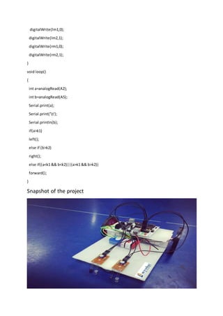
  • 26. digitalWrite(lm1,0); digitalWrite(lm2,1); digitalWrite(rm1,0); digitalWrite(rm2,1); } void loop() { int a=analogRead(A2); int b=analogRead(A5); Serial.print(a); Serial.print('t'); Serial.println(b); if(a>k1) left(); else if (b>k2) right(); else if((a<k1 && b<k2)||(a>k1 && b>k2)) forward(); } Snapshot of the project
  • 27. Conclusion In this project we have studied and implemented a Line Following Robot using Arduino Uno. The programming and interface of microcontroller has been mastered during the implementation. The Track Followerrobotisone of the outcomesof implementationof withmicrocontrolleronsingle board. This robot can be autonomous if it is run by 4 AA batteries. There are certain advantages of this robot. They are as:  Increased productivity, safety, efficiency, quality of products  Can work in hazardous environments, no need for support  Need no environmental comforts  Have repeatable precision at all times  Can be more accurate than humans  Have many capabilities beyond those of humans  Can process multiple stimuli/tasks simultaneously  .A robot can work without sleep. So it can work 24/7/365  Apart from advantages there are some disadvantages too. Robotstake the place of manyhumansinplaceslike factories.Sothe peoplehave tofindnew jobsor be retrained. So a MAJOR disadvantage is that the robots take the place of humans in several situations. Another disadvantage is that there is quite a high initial cost for the robot and the software and equipment that you need to use with the robot