SlideShare a Scribd company logo
CNC PARTCNC PART
PROGRAMMINGPROGRAMMING
PART PROGRAMPART PROGRAM
• A part program is a series of coded instructions required toA part program is a series of coded instructions required to
produce a part. It controls the movement of the machine toolproduce a part. It controls the movement of the machine tool
and the on/off control of auxiliary functions such as spindleand the on/off control of auxiliary functions such as spindle
rotation and coolant. The coded instructions are composed ofrotation and coolant. The coded instructions are composed of
letters, numbers and symbols and are arranged in a format ofletters, numbers and symbols and are arranged in a format of
functional blocks as in the following examplefunctional blocks as in the following example
N10 G01 X5.0 Y2.5 F15.0N10 G01 X5.0 Y2.5 F15.0
   |       |       |         |        |   |       |       |         |        |
   |       |       |         |       Feed rate (15 in/min)   |       |       |         |       Feed rate (15 in/min)
   |       |       |        Y-coordinate (2.5")   |       |       |        Y-coordinate (2.5")
   |       |      X-coordinate (5.0")   |       |      X-coordinate (5.0")
   |      Linear interpolation mode   |      Linear interpolation mode
  Sequence number  Sequence number
PROGRAM INPUT DEVICEPROGRAM INPUT DEVICE
• The program input device is the mechanism forThe program input device is the mechanism for
part programs to be entered into the CNCpart programs to be entered into the CNC
control. Thcontrol. The moste most commonly used programcommonly used program
input devices areinput devices are keyboardskeyboards,, punched tapepunched tape
reader, diskette drivers, throgh RS 232 serialreader, diskette drivers, throgh RS 232 serial
ports and networksports and networks..
MACHINE CONTROL UNITMACHINE CONTROL UNIT
The machine control unit (MCU) is the heart of a CNC system. ItThe machine control unit (MCU) is the heart of a CNC system. It
is used to perform the following functions:is used to perform the following functions:
• Read coded instructionsRead coded instructions
• Decode coded instructionsDecode coded instructions
• Implement interpolations (linear, circular, and helical) to generateImplement interpolations (linear, circular, and helical) to generate
axis motion commandsaxis motion commands
• Feed axis motion commands to the amplifier circuits for drivingFeed axis motion commands to the amplifier circuits for driving
the axis mechanismsthe axis mechanisms
• Receive the feedback signals of position and speed for each driveReceive the feedback signals of position and speed for each drive
axisaxis
• Implement auxiliary control functions such as coolant or spindleImplement auxiliary control functions such as coolant or spindle
on/off, and tool changeon/off, and tool change
CNC PROGRAMMINGCNC PROGRAMMING
• Offline programmingOffline programming linked to CADlinked to CAD
programs.programs.
• Conversational programmingConversational programming by the operator.by the operator.
• MDIMDI ~ Manual Data Input.~ Manual Data Input.
• Manual ControlManual Control using jog buttons orusing jog buttons or
`electronic handwheel'.`electronic handwheel'.
• Word-Address CodingWord-Address Coding using standard G-codesusing standard G-codes
and M-codes.and M-codes.
The position of the tool is describedThe position of the tool is described
by using a Cartesian coordinateby using a Cartesian coordinate
system. If (0,0,0) position can besystem. If (0,0,0) position can be
described by the operator, then it isdescribed by the operator, then it is
calledcalled floating zerofloating zero..
In defining the motion of the toolIn defining the motion of the tool
from one point to another,from one point to another,
eithereither absoluteabsolute positioningpositioning mode ormode or
incrementalincremental positioningpositioning modemode
can be used.can be used.
1.1. Absolute positioningAbsolute positioning. In this mode, the. In this mode, the
desired target position of the tool for adesired target position of the tool for a
particular move is given relative to the originparticular move is given relative to the origin
point of the program.point of the program.
2.2. Incremental positioningIncremental positioning. In this mode, the. In this mode, the
next target position for the tool is givennext target position for the tool is given
relative to the current toolrelative to the current tool position.position.
Structure of an NC Part Program:Structure of an NC Part Program:
Commands are input into the controller in
units called blocks or statements.
Block Format:
1. Fixed sequential format
2. Tab sequential format
3. Word address format
EXAMPLE:EXAMPLE:
Assume that a drilling operation is to be
programmed as:
1. The tool is positioned at (25.4,12.5,0) by a
rapid movement.
2. The tool is then advanced -10 mm in the z
direction at a feed rate of 500 mm/min., with the
flood coolant on.
3.The is then retracted back 10 mm at the rapid
feed rate, and the coolant is turned off.
1. Fixed sequential format1. Fixed sequential format
0050 00 +0025400 +0012500 +0000000 0000 000050 00 +0025400 +0012500 +0000000 0000 00
0060 01 +0025400 +0012500 -0010000 0500 080060 01 +0025400 +0012500 -0010000 0500 08
0070 00 +0025400 +0012500 +0000000 0000 090070 00 +0025400 +0012500 +0000000 0000 09
2. Tab sequential format
0050 TAB 00 TAB +0025400 TAB +0012500 TAB +0000000 TA
0060 TAB 01 TAB TAB TAB -0010000 TAB 0500 TAB 08
0070 TAB 00 TAB TAB TAB -0000000 TAB 0000 TAB 09
3. Word address format
N50 G00 X25400 Y125 Z0 F0
N60 G01 Z-10000 F500 M08
N70 G00 Z0 M09
Modal commandsModal commands: Commands issued in the: Commands issued in the
NC program that will stay in effect until it isNC program that will stay in effect until it is
changed by some other command, like, feedchanged by some other command, like, feed
rate selection, coolant selection, etc.rate selection, coolant selection, etc.
Nonmodal commandsNonmodal commands: Commands that are: Commands that are
effective only when issued and whose effectseffective only when issued and whose effects
are lost for subsequent commands, like, aare lost for subsequent commands, like, a
dwell command which instructs the tool todwell command which instructs the tool to
remain in a given configuration for a givenremain in a given configuration for a given
amount of time.amount of time.
INFORMATION NEEDED by aINFORMATION NEEDED by a
CNCCNC
1. Preparatory Information: units, incremental or absolute
positioning
2. Coordinates: X,Y,Z, RX,RY,RZ
3. Machining Parameters: Feed rate and spindle speed
4. Coolant Control: On/Off, Flood, Mist
5. Tool Control: Tool and tool parameters
6. Cycle Functions: Type of action required
7. Miscellaneous Control: Spindle on/off, direction of rotation,
stops for part movement
This information is conveyed to the machine through a set
of instructions arranged in a desired sequence – Program.
BLOCK FORMATBLOCK FORMAT
Sample BlockSample Block
N135 G01 X1.0 Y1.0 Z0.125 F5
• Restrictions on CNC blocks
• Each may contain only one tool move
• Each may contain any number of non-tool move G-codes
• Each may contain only one feedrate
• Each may contain only one specified tool or spindle speed
• The block numbers should be sequential
• Both the program start flag and the program number must be
independent of all other commands (on separate lines)
• The data within a block should follow the sequence shown in the
above sample block
WORD-ADDRESS CODINGWORD-ADDRESS CODING
• N5 G90 G20N5 G90 G20
• N10 M06 T3N10 M06 T3
• N15 M03 S1250N15 M03 S1250
• N20 G00 X1 Y1N20 G00 X1 Y1
• N25 Z0.1N25 Z0.1
• N30 G01 Z-0.125 F5N30 G01 Z-0.125 F5
• N35 X3 Y2 F10N35 X3 Y2 F10
• N40 G00 Z1N40 G00 Z1
• N45 X0 Y0N45 X0 Y0
• N50 M05N50 M05
• N55 M30N55 M30
Example CNC ProgramExample CNC Program
Each instruction to the machine
consists of a letter followed by a
number.
Each letter is associated with a
specific type of action or piece of
information needed by the machine.
Letters used in Codes
N,G,X,Y,Z,A,B,C,I,J,K,F,S,T,R,M
G CodesG Codes
• G00G00 Rapid traverseRapid traverse
• G01 Linear interpolationG01 Linear interpolation
• G02G02 Circular interpolation,Circular interpolation,
CWCW
• G03 Circular interpolation,G03 Circular interpolation,
CCWCCW
• G04 DwellG04 Dwell
• G08 AccelerationG08 Acceleration
• G09 DecelerationG09 Deceleration
• G17 X-Y PlaneG17 X-Y Plane
• G18 Z-X PlaneG18 Z-X Plane
• G19 Y-Z PlaneG19 Y-Z Plane
• G20 Inch Units (G70)G20 Inch Units (G70)
• G21 Metric Units (G71)G21 Metric Units (G71)
• G40 Cutter compensation –G40 Cutter compensation –
cancelcancel
• G41 Cutter compensation –G41 Cutter compensation –
leftleft
• G42 Cutter compensation-G42 Cutter compensation-
rightright
• G70 Inch formatG70 Inch format
• G71 Metric formatG71 Metric format
• G74 Full-circleG74 Full-circle programmingprogramming
offoff
• G75 Full-circle programmingG75 Full-circle programming
onon
• G80 Fixed-cycle cancelG80 Fixed-cycle cancel
• G81-G89 Fixed cyclesG81-G89 Fixed cycles
• G90 Absolute dimensionsG90 Absolute dimensions
• G91 Incremental dimensionsG91 Incremental dimensions
M CodesM Codes
• M00M00 Program stopProgram stop
• M01M01 Optional program stopOptional program stop
• M02M02 Program endProgram end
• M03M03 Spindle on clockwiseSpindle on clockwise
• M04M04 Spindle on counterclockwiseSpindle on counterclockwise
• M05M05 Spindle stopSpindle stop
• M06M06 Tool changeTool change
• M08M08 Coolant onCoolant on
• M09M09 Coolant offCoolant off
• M10M10 Clamps onClamps on
• M11M11 Clamps offClamps off
• M30M30 Program stop, reset to startProgram stop, reset to start
N CodesN Codes
• Gives anGives an identifying number for eachidentifying number for each block ofblock of
information.information.
• It is generally good practice toIt is generally good practice to increment eachincrement each
block number byblock number by 5 or 10 to allow additional5 or 10 to allow additional
blocks to be inserted if futureblocks to be inserted if future changes arechanges are
required.required.
X,Y, and Z CodesX,Y, and Z Codes
• X, Y, and ZX, Y, and Z codes are used tocodes are used to specify thespecify the
coordinate axis.coordinate axis.
• Number following the codeNumber following the code defines thedefines the
coordinate at the endcoordinate at the end of the move relative to anof the move relative to an
incremental or absoluteincremental or absolute reference point.reference point.
I,J, and K CodesI,J, and K Codes
• I, J, and KI, J, and K codes are used tocodes are used to specify thespecify the
coordinate axiscoordinate axis when defining the center of awhen defining the center of a
circle.circle.
• Number following the codeNumber following the code defines thedefines the
respective coordinaterespective coordinate for the center of the circle.for the center of the circle.
FF,,SS, and, and TT CodesCodes
• F-codeF-code: used to specify the feed: used to specify the feed raterate
• S-codeS-code: used to specify the: used to specify the spindle speedspindle speed
• T-codeT-code: used to specify the tool: used to specify the tool identificationidentification
number associatednumber associated with the tool to be used inwith the tool to be used in
subsequent operations.subsequent operations.
Application of Some CodesApplication of Some Codes
G01 Linear InterpolationG01 Linear Interpolation
Format: N_ G01 X_ Y_ Z_ F_Format: N_ G01 X_ Y_ Z_ F_
• Linear Interpolation results in a straight line feedLinear Interpolation results in a straight line feed
move.move.
• Unless tool compensation is used, theUnless tool compensation is used, the
coordinates arecoordinates are associated with the centerline ofassociated with the centerline of
the tool.the tool.
Application of Some CodesApplication of Some Codes
G01 Linear InterpolationG01 Linear Interpolation
• . As an example, for the motion that occurs in. As an example, for the motion that occurs in
x-y plane with the same maximum speed for thex-y plane with the same maximum speed for the
x- and y-axis, initial motion is at an angle of 45ox- and y-axis, initial motion is at an angle of 45o
to the axes until motion in one ofto the axes until motion in one of
• the axes is completed and then the balance ofthe axes is completed and then the balance of
the motion occurs in the other axis. This isthe motion occurs in the other axis. This is
calledcalled point-to-point motionpoint-to-point motion..
Application of Some CodesApplication of Some Codes
G01 Linear InterpolationG01 Linear Interpolation
5
10
15
20
25
5 10 15 20 25 30
A
B C
Positioning motion from A to C
N10 G00 X30000 Y20000 F0
N10N10 G00 X1G00 X1 ZZ11
NN115 Z0.15 Z0.1
NN2020 G01 Z-0.125 F5G01 Z-0.125 F5
NN2255 X2 Z2X2 Z2 F10F10
G01 Linear InterpolationG01 Linear Interpolation
X
Z
G02 Circular InterpolationG02 Circular Interpolation
• G02 is also a preparatory function to specify thatG02 is also a preparatory function to specify that
the tool should be moved to a specified locationthe tool should be moved to a specified location
along a circular path in a clockwise direction. Inalong a circular path in a clockwise direction. In
order to specify the path to the MCU, the endorder to specify the path to the MCU, the end
point of the arc and the location of the center ofpoint of the arc and the location of the center of
the arc should be specified. Within the block inthe arc should be specified. Within the block in
which the G02 code is programmed, the centerwhich the G02 code is programmed, the center
of the arc is given by specifying its locationof the arc is given by specifying its location
relative to the start of the arc.relative to the start of the arc.
G02 Circular Interpolation (CW)G02 Circular Interpolation (CW)
• The G02 commandThe G02 command requiresrequires
an endpoint and a radiusan endpoint and a radius inin
order to cut the arc.order to cut the arc.
• I,J, and K are relativeI,J, and K are relative to theto the
start point.start point.
N_ G02 X2 Y1 I0 J-1 F10N_ G02 X2 Y1 I0 J-1 F10
oror
N_ G02 X2 Y1 R1N_ G02 X2 Y1 R1
G02 Circular Interpolation (CW)G02 Circular Interpolation (CW)
5
10
15
20
25
5 10 15 20 25 30
C
C
Circular interpolation from A to B
about a circle centered at C
N10 G02 X20000 Y10000
I5000 J15000 F2500
A
B
I=5
J=15
The sequence of some machining operations
is may be the same for any part and for any
machine. For example, drilling a hole involves
the following steps:
Position the tool above the point where the
hole will be drilled
Set the correct spindle speed
Feed the tool into the workpiece at a
controlled feed rate to a predetermined depth
Retract the tool at a rapid rate to just above
the point where the hole started
Canned Cycles
Some Commonly Used Canned Cycle
Code Function Down feed At bottom Retracti
on
G81 Drilling Continuous
feed
No action Rapid
G82 Spot face,
counterbore
Continuous
feed
Dwell Rapid
G83 Deep hole drilling Peck No action Rapid
G84 Tapping Continuous
feed
Reverse
spindle
Feed
rate
G85 Through boring(in
& out)
Continuous
feed
No action Feed
rate
G86 Through boring(in
only)
Continuous
feed
Stop
spindle
Rapid
G81 ILLUSTRATIONG81 ILLUSTRATION
Three Main parts of a CNC programThree Main parts of a CNC program
• N5 G90 G2N5 G90 G211 (Absolute units,(Absolute units, metricmetric))
• N10 M06 T2N10 M06 T2 (Stop for tool change, use(Stop for tool change, use
tool # 2)tool # 2)
• N15 M03 S1200N15 M03 S1200 (Turn the spindle on CW(Turn the spindle on CW
toto 1200 rpm)1200 rpm)
Part 1- Program PetupPart 1- Program Petup
Three Main parts of a CNC programThree Main parts of a CNC program
• N20 G00 X1 Y1N20 G00 X1 Y1 (Rapid to X1,Y1 from origin(Rapid to X1,Y1 from origin
point)point)
• N25 Z0.125N25 Z0.125 (Rapid down to Z0.125)(Rapid down to Z0.125)
• N30 G01 Z-0.125 FN30 G01 Z-0.125 F100100 (Feed down to Z-0.125 at(Feed down to Z-0.125 at
100 mm/100 mm/mminin))
• N35 G01 X2 Y2N35 G01 X2 Y2 (Feed diagonally to X2,Y2)(Feed diagonally to X2,Y2)
• N40 G00 Z1N40 G00 Z1 (Rapid up to Z1)(Rapid up to Z1)
• N45 X0 Y0N45 X0 Y0 (Rapid to X0,Y0)(Rapid to X0,Y0)
Part 2- Chip RemovalPart 2- Chip Removal
Three Main parts of a CNC programThree Main parts of a CNC program
• N50 M05N50 M05 (Turn the spindle off)(Turn the spindle off)
• N55 MN55 M0000 ((PProgramrogram stopstop))
Part 3- System ShutdownPart 3- System Shutdown
EXAMPLE OPERATION on CNCEXAMPLE OPERATION on CNC
MILLING MACHINEMILLING MACHINE
G-CODE PROGRAMG-CODE PROGRAM
• First pass : conventional mill to a
depth of 0.125 around edge profile.
Tool 1 is a ½ inch dia. end mill.
%
:1002
N5 G90 G20
N10 M06 T1
N15 M03 S1200
N20 G00 X0.125 Y0.125
N30 Z0.125
N35 G01 Z-0.125 F5
N40 X3.875
N45 Y4.125
N50 X0.125
N55 Y0.125
• Second pass:
conventional mill to a
depth of 0.25 around
edge profile.
N35 Z-0.250
N40 X3.875
N45 Y4.125
N50 X0.125
N55 Y0.125
N60 Z0.125
• Third pass: conventional
mill to a depth of 0.125
around pocket profile.
N65 G00 X1.25 Y1.0
N70 G01 Z-0.125 F5
N75 X1.75
N80 Y2.5
N85 X1.25
N90 Y1.0
N95 Z0.125
• Fourth pass: climb mill
to a depth of 0.125
across remaining
material.
N100 Y2.125
N105 X2.625
N110 Z0.125
N115 G00 X-5 Y-5 Z5
N120 M05
N125 M30
Advanced features:Advanced features:
• Execution of the part of the program in a rotatedExecution of the part of the program in a rotated
or mirrored position.or mirrored position.
• Ability to scale the program and produce larger orAbility to scale the program and produce larger or
smaller programs.smaller programs.
• Three dimensional circular interpolation whichThree dimensional circular interpolation which
produces a helical shape.produces a helical shape.
• Parabolic and cubic interpolation.Parabolic and cubic interpolation.
• NC program preparation may be tedious and difficultNC program preparation may be tedious and difficult
if the part to be machined has a complex geometry.if the part to be machined has a complex geometry.
The main difficulty is to find out the cutter locationsThe main difficulty is to find out the cutter locations
during the machining. Computers may be used toduring the machining. Computers may be used to
assist the programmers in preparing the NC codes.assist the programmers in preparing the NC codes.
Computer Aided Part Programming:
Advantages of applying computer-aided partAdvantages of applying computer-aided part
programming include the following:programming include the following:
• 1. It reduces the manual calculations involves in1. It reduces the manual calculations involves in
determining the geometric characteristics of the part.determining the geometric characteristics of the part.
• It provides the cutter path simulation.It provides the cutter path simulation.
• It provides tool collision checking.It provides tool collision checking.
• It shortens the program preparation time.It shortens the program preparation time.
• It makes the program preparation easier.It makes the program preparation easier.
• The Aerospace Industries Association sponsored theThe Aerospace Industries Association sponsored the
work that led to the first part programming language,work that led to the first part programming language,
developed in MIT in 1955.developed in MIT in 1955.
• This was called:This was called: Automatically Programmed ToolsAutomatically Programmed Tools (APT).(APT).
• APT is an English like simple programming languageAPT is an English like simple programming language
which basically produce thewhich basically produce the Cutter LocationCutter Location (CL) data.(CL) data.
• Using the cutter location data, the program canUsing the cutter location data, the program can
generate the actual NC codes by using agenerate the actual NC codes by using a
postprocessor .postprocessor .
• The output of any CAD package include theThe output of any CAD package include the
geometric data of the part to be machined. Therefore,geometric data of the part to be machined. Therefore,
many CAD/CAM package can produce cuttermany CAD/CAM package can produce cutter
location (CL) data to be used for NC code generation.location (CL) data to be used for NC code generation.
• There is still to be a process planning module for aThere is still to be a process planning module for a
workable NC code generation.workable NC code generation.
• Some of the CAD/CAM packages that have the NCSome of the CAD/CAM packages that have the NC
code generation capabilities are Computervision,code generation capabilities are Computervision,
CATIA, CADAM, ProEngineer, MechanicalDesktopCATIA, CADAM, ProEngineer, MechanicalDesktop
(Auto Desk).(Auto Desk).
CAD/CAM Based Part Programming:CAD/CAM Based Part Programming:

More Related Content

What's hot (20)

PPTX
Cnc milling
kailashgavare
 
PPT
CNC Turning.ppt
HimanshuPathak368871
 
PPTX
CNC Programming
rajguptanitw
 
PPT
Cnc lathe
kailashgavare
 
PPTX
CNC AND ITS COMPONENTS
ananya0122
 
PDF
Cnc tooling for cnc machine(130670119596)
Kushal Shah
 
PPTX
CNC Circular Interpolation
Sandeep Adkar
 
PPTX
Canned cycle
aman1312
 
PPT
Cnc turning(Fanuc system)
NavinBurnwal1
 
PPTX
Tool presetting
nilesh vishwani
 
PPTX
Cnc milling turning
Salman Jailani
 
PPTX
Gear shaping
fadwala07
 
PPTX
Introduction to CNC machine and Hardware.
aman1312
 
PPT
CNC Milling (fanuc system)
NavinBurnwal1
 
PDF
Chapter 2 constructional feature of cnc machine
RAHUL THAKER
 
PDF
Cnc machine tools
ftesv
 
PPTX
CNC Turning and Milling centres
Achyuth Padmanabh
 
PPTX
Unit V CNC Machining
laxtwinsme
 
PPTX
NC AND CNC
SIVASHANKAR N
 
PPTX
Linear motion guideways
Akhil Krishnan G
 
Cnc milling
kailashgavare
 
CNC Turning.ppt
HimanshuPathak368871
 
CNC Programming
rajguptanitw
 
Cnc lathe
kailashgavare
 
CNC AND ITS COMPONENTS
ananya0122
 
Cnc tooling for cnc machine(130670119596)
Kushal Shah
 
CNC Circular Interpolation
Sandeep Adkar
 
Canned cycle
aman1312
 
Cnc turning(Fanuc system)
NavinBurnwal1
 
Tool presetting
nilesh vishwani
 
Cnc milling turning
Salman Jailani
 
Gear shaping
fadwala07
 
Introduction to CNC machine and Hardware.
aman1312
 
CNC Milling (fanuc system)
NavinBurnwal1
 
Chapter 2 constructional feature of cnc machine
RAHUL THAKER
 
Cnc machine tools
ftesv
 
CNC Turning and Milling centres
Achyuth Padmanabh
 
Unit V CNC Machining
laxtwinsme
 
NC AND CNC
SIVASHANKAR N
 
Linear motion guideways
Akhil Krishnan G
 

Viewers also liked (20)

PPT
CNC Machines
pratik207
 
PPT
part programming (cnc)
SK MD RAIJUL HAQUE
 
PPTX
NC, CNC & DNC Machine
Nilraj Vasandia
 
PPT
CNC Programmingmodifies examination 1
Prof. S.Rajendiran
 
PPT
CNC Programmingmodifies1
Prof. S.Rajendiran
 
PPTX
Recent Advancement of CNC Technology
Debiprasad Sena
 
PPTX
CNC Seminar
Bheem Singh Chaudhary
 
DOC
Introduction to cnc machines (1)
someshking
 
PPTX
DEVELOPING CNC PROGRAM FOR THE MANUFACTURING OF GUIDE
Rebally Aditya
 
PDF
Lecture 17 position systems of nc [compatibility mode]
Dr.Muftooh Ur Rehman Siddiqi
 
PPTX
Nc part programming
Vemulapalli Das
 
PPT
CNC Programming
Mal Moran
 
PPT
Cnc lathe ppt
99759067
 
DOCX
Computer numerical controlled machine project
Muhammad Zaighum Farooq
 
PPT
Cnc cutting tools
Rakesh Raki
 
PDF
Cncpresentation CNC lathe machine
Haseeb Butt
 
PPTX
CNC AND ITS COMPONENTS
ananya0122
 
PPT
Nc programming
Sudhir Reddy
 
PDF
Friction problems
faizankhan260690
 
CNC Machines
pratik207
 
part programming (cnc)
SK MD RAIJUL HAQUE
 
NC, CNC & DNC Machine
Nilraj Vasandia
 
CNC Programmingmodifies examination 1
Prof. S.Rajendiran
 
CNC Programmingmodifies1
Prof. S.Rajendiran
 
Recent Advancement of CNC Technology
Debiprasad Sena
 
Introduction to cnc machines (1)
someshking
 
DEVELOPING CNC PROGRAM FOR THE MANUFACTURING OF GUIDE
Rebally Aditya
 
Lecture 17 position systems of nc [compatibility mode]
Dr.Muftooh Ur Rehman Siddiqi
 
Nc part programming
Vemulapalli Das
 
CNC Programming
Mal Moran
 
Cnc lathe ppt
99759067
 
Computer numerical controlled machine project
Muhammad Zaighum Farooq
 
Cnc cutting tools
Rakesh Raki
 
Cncpresentation CNC lathe machine
Haseeb Butt
 
CNC AND ITS COMPONENTS
ananya0122
 
Nc programming
Sudhir Reddy
 
Friction problems
faizankhan260690
 
Ad

Similar to Cnc part programming 4 unit (20)

PPTX
CNC PART PROGRAMMING.pptx
AtharvaJagtap15
 
PPTX
CNC part programming
jntuhcej
 
PPTX
CAD-CAM-Module-4-Subtractive-Manufacturing-1-print.pptx
sahils237192101
 
PPT
Cnc1
sundar sivam
 
PPT
CNC1.ppt
WondererBack
 
PPT
CNC1.ppt
RuturajTanwade
 
PPT
CNC1 (1).ppt
WondererBack
 
PPT
CNC Programing method introduction _ Basic
tungtien300479
 
PPT
CNC Machining part for engineering studenPart-1.ppt
ShadatHossain12
 
PPT
CNfbhfhhfhdhhdhhdhdhhdhhdhdhhdhfhfhhfhdC_1.ppt
mahendramech22
 
PPT
CNC1.ppt
PrakashBehera40
 
PDF
7-CNC_Programming_For_Lathe_na_eng.pdf
ssuser46f1ac
 
PPTX
Manual part programming
jntuhcej
 
PDF
Cnc programming basics.doc
Soekarno Revolusi
 
PPT
CIMS Lab.ppt
1234173916
 
PDF
CNC PROGRAMMING.pdf
AbhiKarn2
 
PDF
Lecture 25.pdf
kprudhviraj5
 
PPTX
COMPUTER NUMERICAL CONTROL MACHINE
Gopal Bhargava
 
PPTX
CAD CAM Exercise CNC PROGRAMMING LATHE.pptx
Praveen Kumar
 
CNC PART PROGRAMMING.pptx
AtharvaJagtap15
 
CNC part programming
jntuhcej
 
CAD-CAM-Module-4-Subtractive-Manufacturing-1-print.pptx
sahils237192101
 
CNC1.ppt
WondererBack
 
CNC1.ppt
RuturajTanwade
 
CNC1 (1).ppt
WondererBack
 
CNC Programing method introduction _ Basic
tungtien300479
 
CNC Machining part for engineering studenPart-1.ppt
ShadatHossain12
 
CNfbhfhhfhdhhdhhdhdhhdhhdhdhhdhfhfhhfhdC_1.ppt
mahendramech22
 
CNC1.ppt
PrakashBehera40
 
7-CNC_Programming_For_Lathe_na_eng.pdf
ssuser46f1ac
 
Manual part programming
jntuhcej
 
Cnc programming basics.doc
Soekarno Revolusi
 
CIMS Lab.ppt
1234173916
 
CNC PROGRAMMING.pdf
AbhiKarn2
 
Lecture 25.pdf
kprudhviraj5
 
COMPUTER NUMERICAL CONTROL MACHINE
Gopal Bhargava
 
CAD CAM Exercise CNC PROGRAMMING LATHE.pptx
Praveen Kumar
 
Ad

More from palanivendhan (14)

PDF
Super surplus-brochure
palanivendhan
 
PPTX
Non patentable inventions
palanivendhan
 
PPT
Quality function deployment
palanivendhan
 
PPTX
Management system
palanivendhan
 
PPT
failure modes and effects analysis (fmea)
palanivendhan
 
PPT
new quality tools
palanivendhan
 
PPTX
MATERIALS TECHNOLOGY
palanivendhan
 
PPTX
PHASE DIAGRAMS
palanivendhan
 
PPTX
FRACTURE BEHAVIOUR
palanivendhan
 
PPTX
MATERIALS TECHNOLOGY
palanivendhan
 
PPT
Fundamentals of cutting
palanivendhan
 
PDF
Cnc 2 unit palanivendhan cnc elements
palanivendhan
 
PDF
Cam 1 unit palanivendhan manufacturin systems
palanivendhan
 
PPT
Directing,principles of management,palanivendhan
palanivendhan
 
Super surplus-brochure
palanivendhan
 
Non patentable inventions
palanivendhan
 
Quality function deployment
palanivendhan
 
Management system
palanivendhan
 
failure modes and effects analysis (fmea)
palanivendhan
 
new quality tools
palanivendhan
 
MATERIALS TECHNOLOGY
palanivendhan
 
PHASE DIAGRAMS
palanivendhan
 
FRACTURE BEHAVIOUR
palanivendhan
 
MATERIALS TECHNOLOGY
palanivendhan
 
Fundamentals of cutting
palanivendhan
 
Cnc 2 unit palanivendhan cnc elements
palanivendhan
 
Cam 1 unit palanivendhan manufacturin systems
palanivendhan
 
Directing,principles of management,palanivendhan
palanivendhan
 

Recently uploaded (20)

PDF
Wikinomics How Mass Collaboration Changes Everything Don Tapscott
wcsqyzf5909
 
PPT
M&A5 Q1 1 differentiate evolving early Philippine conventional and contempora...
ErlizaRosete
 
PPTX
Photo chemistry Power Point Presentation
mprpgcwa2024
 
PDF
THE PSYCHOANALYTIC OF THE BLACK CAT BY EDGAR ALLAN POE (1).pdf
nabilahk908
 
PPTX
How to Configure Refusal of Applicants in Odoo 18 Recruitment
Celine George
 
PPTX
Peer Teaching Observations During School Internship
AjayaMohanty7
 
PDF
DIGESTION OF CARBOHYDRATES ,PROTEINS AND LIPIDS
raviralanaresh2
 
PPTX
How to Manage Wins & Losses in Odoo 18 CRM
Celine George
 
DOCX
DLL english grade five goof for one week
FlordelynGonzales1
 
DOCX
MUSIC AND ARTS 5 DLL MATATAG LESSON EXEMPLAR QUARTER 1_Q1_W1.docx
DianaValiente5
 
PPTX
Iván Bornacelly - Presentation of the report - Empowering the workforce in th...
EduSkills OECD
 
PDF
Nanotechnology and Functional Foods Effective Delivery of Bioactive Ingredien...
rmswlwcxai8321
 
PDF
VCE Literature Section A Exam Response Guide
jpinnuck
 
PDF
Free eBook ~100 Common English Proverbs (ebook) pdf.pdf
OH TEIK BIN
 
PPTX
ESP 10 Edukasyon sa Pagpapakatao PowerPoint Lessons Quarter 1.pptx
Sir J.
 
PDF
Andreas Schleicher_Teaching Compass_Education 2040.pdf
EduSkills OECD
 
DOCX
ANNOTATION on objective 10 on pmes 2022-2025
joviejanesegundo1
 
PPTX
How to Add New Item in CogMenu in Odoo 18
Celine George
 
PDF
Rapid Mathematics Assessment Score sheet for all Grade levels
DessaCletSantos
 
PPT
M&A5 Q1 1 differentiate evolving early Philippine conventional and contempora...
ErlizaRosete
 
Wikinomics How Mass Collaboration Changes Everything Don Tapscott
wcsqyzf5909
 
M&A5 Q1 1 differentiate evolving early Philippine conventional and contempora...
ErlizaRosete
 
Photo chemistry Power Point Presentation
mprpgcwa2024
 
THE PSYCHOANALYTIC OF THE BLACK CAT BY EDGAR ALLAN POE (1).pdf
nabilahk908
 
How to Configure Refusal of Applicants in Odoo 18 Recruitment
Celine George
 
Peer Teaching Observations During School Internship
AjayaMohanty7
 
DIGESTION OF CARBOHYDRATES ,PROTEINS AND LIPIDS
raviralanaresh2
 
How to Manage Wins & Losses in Odoo 18 CRM
Celine George
 
DLL english grade five goof for one week
FlordelynGonzales1
 
MUSIC AND ARTS 5 DLL MATATAG LESSON EXEMPLAR QUARTER 1_Q1_W1.docx
DianaValiente5
 
Iván Bornacelly - Presentation of the report - Empowering the workforce in th...
EduSkills OECD
 
Nanotechnology and Functional Foods Effective Delivery of Bioactive Ingredien...
rmswlwcxai8321
 
VCE Literature Section A Exam Response Guide
jpinnuck
 
Free eBook ~100 Common English Proverbs (ebook) pdf.pdf
OH TEIK BIN
 
ESP 10 Edukasyon sa Pagpapakatao PowerPoint Lessons Quarter 1.pptx
Sir J.
 
Andreas Schleicher_Teaching Compass_Education 2040.pdf
EduSkills OECD
 
ANNOTATION on objective 10 on pmes 2022-2025
joviejanesegundo1
 
How to Add New Item in CogMenu in Odoo 18
Celine George
 
Rapid Mathematics Assessment Score sheet for all Grade levels
DessaCletSantos
 
M&A5 Q1 1 differentiate evolving early Philippine conventional and contempora...
ErlizaRosete
 

Cnc part programming 4 unit

  • 2. PART PROGRAMPART PROGRAM • A part program is a series of coded instructions required toA part program is a series of coded instructions required to produce a part. It controls the movement of the machine toolproduce a part. It controls the movement of the machine tool and the on/off control of auxiliary functions such as spindleand the on/off control of auxiliary functions such as spindle rotation and coolant. The coded instructions are composed ofrotation and coolant. The coded instructions are composed of letters, numbers and symbols and are arranged in a format ofletters, numbers and symbols and are arranged in a format of functional blocks as in the following examplefunctional blocks as in the following example N10 G01 X5.0 Y2.5 F15.0N10 G01 X5.0 Y2.5 F15.0    |       |       |         |        |   |       |       |         |        |    |       |       |         |       Feed rate (15 in/min)   |       |       |         |       Feed rate (15 in/min)    |       |       |        Y-coordinate (2.5")   |       |       |        Y-coordinate (2.5")    |       |      X-coordinate (5.0")   |       |      X-coordinate (5.0")    |      Linear interpolation mode   |      Linear interpolation mode   Sequence number  Sequence number
  • 3. PROGRAM INPUT DEVICEPROGRAM INPUT DEVICE • The program input device is the mechanism forThe program input device is the mechanism for part programs to be entered into the CNCpart programs to be entered into the CNC control. Thcontrol. The moste most commonly used programcommonly used program input devices areinput devices are keyboardskeyboards,, punched tapepunched tape reader, diskette drivers, throgh RS 232 serialreader, diskette drivers, throgh RS 232 serial ports and networksports and networks..
  • 4. MACHINE CONTROL UNITMACHINE CONTROL UNIT The machine control unit (MCU) is the heart of a CNC system. ItThe machine control unit (MCU) is the heart of a CNC system. It is used to perform the following functions:is used to perform the following functions: • Read coded instructionsRead coded instructions • Decode coded instructionsDecode coded instructions • Implement interpolations (linear, circular, and helical) to generateImplement interpolations (linear, circular, and helical) to generate axis motion commandsaxis motion commands • Feed axis motion commands to the amplifier circuits for drivingFeed axis motion commands to the amplifier circuits for driving the axis mechanismsthe axis mechanisms • Receive the feedback signals of position and speed for each driveReceive the feedback signals of position and speed for each drive axisaxis • Implement auxiliary control functions such as coolant or spindleImplement auxiliary control functions such as coolant or spindle on/off, and tool changeon/off, and tool change
  • 5. CNC PROGRAMMINGCNC PROGRAMMING • Offline programmingOffline programming linked to CADlinked to CAD programs.programs. • Conversational programmingConversational programming by the operator.by the operator. • MDIMDI ~ Manual Data Input.~ Manual Data Input. • Manual ControlManual Control using jog buttons orusing jog buttons or `electronic handwheel'.`electronic handwheel'. • Word-Address CodingWord-Address Coding using standard G-codesusing standard G-codes and M-codes.and M-codes.
  • 6. The position of the tool is describedThe position of the tool is described by using a Cartesian coordinateby using a Cartesian coordinate system. If (0,0,0) position can besystem. If (0,0,0) position can be described by the operator, then it isdescribed by the operator, then it is calledcalled floating zerofloating zero..
  • 7. In defining the motion of the toolIn defining the motion of the tool from one point to another,from one point to another, eithereither absoluteabsolute positioningpositioning mode ormode or incrementalincremental positioningpositioning modemode can be used.can be used.
  • 8. 1.1. Absolute positioningAbsolute positioning. In this mode, the. In this mode, the desired target position of the tool for adesired target position of the tool for a particular move is given relative to the originparticular move is given relative to the origin point of the program.point of the program. 2.2. Incremental positioningIncremental positioning. In this mode, the. In this mode, the next target position for the tool is givennext target position for the tool is given relative to the current toolrelative to the current tool position.position.
  • 9. Structure of an NC Part Program:Structure of an NC Part Program: Commands are input into the controller in units called blocks or statements. Block Format: 1. Fixed sequential format 2. Tab sequential format 3. Word address format
  • 10. EXAMPLE:EXAMPLE: Assume that a drilling operation is to be programmed as: 1. The tool is positioned at (25.4,12.5,0) by a rapid movement. 2. The tool is then advanced -10 mm in the z direction at a feed rate of 500 mm/min., with the flood coolant on. 3.The is then retracted back 10 mm at the rapid feed rate, and the coolant is turned off.
  • 11. 1. Fixed sequential format1. Fixed sequential format 0050 00 +0025400 +0012500 +0000000 0000 000050 00 +0025400 +0012500 +0000000 0000 00 0060 01 +0025400 +0012500 -0010000 0500 080060 01 +0025400 +0012500 -0010000 0500 08 0070 00 +0025400 +0012500 +0000000 0000 090070 00 +0025400 +0012500 +0000000 0000 09 2. Tab sequential format 0050 TAB 00 TAB +0025400 TAB +0012500 TAB +0000000 TA 0060 TAB 01 TAB TAB TAB -0010000 TAB 0500 TAB 08 0070 TAB 00 TAB TAB TAB -0000000 TAB 0000 TAB 09 3. Word address format N50 G00 X25400 Y125 Z0 F0 N60 G01 Z-10000 F500 M08 N70 G00 Z0 M09
  • 12. Modal commandsModal commands: Commands issued in the: Commands issued in the NC program that will stay in effect until it isNC program that will stay in effect until it is changed by some other command, like, feedchanged by some other command, like, feed rate selection, coolant selection, etc.rate selection, coolant selection, etc. Nonmodal commandsNonmodal commands: Commands that are: Commands that are effective only when issued and whose effectseffective only when issued and whose effects are lost for subsequent commands, like, aare lost for subsequent commands, like, a dwell command which instructs the tool todwell command which instructs the tool to remain in a given configuration for a givenremain in a given configuration for a given amount of time.amount of time.
  • 13. INFORMATION NEEDED by aINFORMATION NEEDED by a CNCCNC 1. Preparatory Information: units, incremental or absolute positioning 2. Coordinates: X,Y,Z, RX,RY,RZ 3. Machining Parameters: Feed rate and spindle speed 4. Coolant Control: On/Off, Flood, Mist 5. Tool Control: Tool and tool parameters 6. Cycle Functions: Type of action required 7. Miscellaneous Control: Spindle on/off, direction of rotation, stops for part movement This information is conveyed to the machine through a set of instructions arranged in a desired sequence – Program.
  • 14. BLOCK FORMATBLOCK FORMAT Sample BlockSample Block N135 G01 X1.0 Y1.0 Z0.125 F5 • Restrictions on CNC blocks • Each may contain only one tool move • Each may contain any number of non-tool move G-codes • Each may contain only one feedrate • Each may contain only one specified tool or spindle speed • The block numbers should be sequential • Both the program start flag and the program number must be independent of all other commands (on separate lines) • The data within a block should follow the sequence shown in the above sample block
  • 15. WORD-ADDRESS CODINGWORD-ADDRESS CODING • N5 G90 G20N5 G90 G20 • N10 M06 T3N10 M06 T3 • N15 M03 S1250N15 M03 S1250 • N20 G00 X1 Y1N20 G00 X1 Y1 • N25 Z0.1N25 Z0.1 • N30 G01 Z-0.125 F5N30 G01 Z-0.125 F5 • N35 X3 Y2 F10N35 X3 Y2 F10 • N40 G00 Z1N40 G00 Z1 • N45 X0 Y0N45 X0 Y0 • N50 M05N50 M05 • N55 M30N55 M30 Example CNC ProgramExample CNC Program Each instruction to the machine consists of a letter followed by a number. Each letter is associated with a specific type of action or piece of information needed by the machine. Letters used in Codes N,G,X,Y,Z,A,B,C,I,J,K,F,S,T,R,M
  • 16. G CodesG Codes • G00G00 Rapid traverseRapid traverse • G01 Linear interpolationG01 Linear interpolation • G02G02 Circular interpolation,Circular interpolation, CWCW • G03 Circular interpolation,G03 Circular interpolation, CCWCCW • G04 DwellG04 Dwell • G08 AccelerationG08 Acceleration • G09 DecelerationG09 Deceleration • G17 X-Y PlaneG17 X-Y Plane • G18 Z-X PlaneG18 Z-X Plane • G19 Y-Z PlaneG19 Y-Z Plane • G20 Inch Units (G70)G20 Inch Units (G70) • G21 Metric Units (G71)G21 Metric Units (G71) • G40 Cutter compensation –G40 Cutter compensation – cancelcancel • G41 Cutter compensation –G41 Cutter compensation – leftleft • G42 Cutter compensation-G42 Cutter compensation- rightright • G70 Inch formatG70 Inch format • G71 Metric formatG71 Metric format • G74 Full-circleG74 Full-circle programmingprogramming offoff • G75 Full-circle programmingG75 Full-circle programming onon • G80 Fixed-cycle cancelG80 Fixed-cycle cancel • G81-G89 Fixed cyclesG81-G89 Fixed cycles • G90 Absolute dimensionsG90 Absolute dimensions • G91 Incremental dimensionsG91 Incremental dimensions
  • 17. M CodesM Codes • M00M00 Program stopProgram stop • M01M01 Optional program stopOptional program stop • M02M02 Program endProgram end • M03M03 Spindle on clockwiseSpindle on clockwise • M04M04 Spindle on counterclockwiseSpindle on counterclockwise • M05M05 Spindle stopSpindle stop • M06M06 Tool changeTool change • M08M08 Coolant onCoolant on • M09M09 Coolant offCoolant off • M10M10 Clamps onClamps on • M11M11 Clamps offClamps off • M30M30 Program stop, reset to startProgram stop, reset to start
  • 18. N CodesN Codes • Gives anGives an identifying number for eachidentifying number for each block ofblock of information.information. • It is generally good practice toIt is generally good practice to increment eachincrement each block number byblock number by 5 or 10 to allow additional5 or 10 to allow additional blocks to be inserted if futureblocks to be inserted if future changes arechanges are required.required.
  • 19. X,Y, and Z CodesX,Y, and Z Codes • X, Y, and ZX, Y, and Z codes are used tocodes are used to specify thespecify the coordinate axis.coordinate axis. • Number following the codeNumber following the code defines thedefines the coordinate at the endcoordinate at the end of the move relative to anof the move relative to an incremental or absoluteincremental or absolute reference point.reference point.
  • 20. I,J, and K CodesI,J, and K Codes • I, J, and KI, J, and K codes are used tocodes are used to specify thespecify the coordinate axiscoordinate axis when defining the center of awhen defining the center of a circle.circle. • Number following the codeNumber following the code defines thedefines the respective coordinaterespective coordinate for the center of the circle.for the center of the circle.
  • 21. FF,,SS, and, and TT CodesCodes • F-codeF-code: used to specify the feed: used to specify the feed raterate • S-codeS-code: used to specify the: used to specify the spindle speedspindle speed • T-codeT-code: used to specify the tool: used to specify the tool identificationidentification number associatednumber associated with the tool to be used inwith the tool to be used in subsequent operations.subsequent operations.
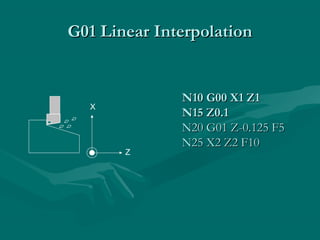
  • 22. Application of Some CodesApplication of Some Codes G01 Linear InterpolationG01 Linear Interpolation Format: N_ G01 X_ Y_ Z_ F_Format: N_ G01 X_ Y_ Z_ F_ • Linear Interpolation results in a straight line feedLinear Interpolation results in a straight line feed move.move. • Unless tool compensation is used, theUnless tool compensation is used, the coordinates arecoordinates are associated with the centerline ofassociated with the centerline of the tool.the tool.
  • 23. Application of Some CodesApplication of Some Codes G01 Linear InterpolationG01 Linear Interpolation • . As an example, for the motion that occurs in. As an example, for the motion that occurs in x-y plane with the same maximum speed for thex-y plane with the same maximum speed for the x- and y-axis, initial motion is at an angle of 45ox- and y-axis, initial motion is at an angle of 45o to the axes until motion in one ofto the axes until motion in one of • the axes is completed and then the balance ofthe axes is completed and then the balance of the motion occurs in the other axis. This isthe motion occurs in the other axis. This is calledcalled point-to-point motionpoint-to-point motion..
  • 24. Application of Some CodesApplication of Some Codes G01 Linear InterpolationG01 Linear Interpolation 5 10 15 20 25 5 10 15 20 25 30 A B C Positioning motion from A to C N10 G00 X30000 Y20000 F0
  • 25. N10N10 G00 X1G00 X1 ZZ11 NN115 Z0.15 Z0.1 NN2020 G01 Z-0.125 F5G01 Z-0.125 F5 NN2255 X2 Z2X2 Z2 F10F10 G01 Linear InterpolationG01 Linear Interpolation X Z
  • 26. G02 Circular InterpolationG02 Circular Interpolation • G02 is also a preparatory function to specify thatG02 is also a preparatory function to specify that the tool should be moved to a specified locationthe tool should be moved to a specified location along a circular path in a clockwise direction. Inalong a circular path in a clockwise direction. In order to specify the path to the MCU, the endorder to specify the path to the MCU, the end point of the arc and the location of the center ofpoint of the arc and the location of the center of the arc should be specified. Within the block inthe arc should be specified. Within the block in which the G02 code is programmed, the centerwhich the G02 code is programmed, the center of the arc is given by specifying its locationof the arc is given by specifying its location relative to the start of the arc.relative to the start of the arc.
  • 27. G02 Circular Interpolation (CW)G02 Circular Interpolation (CW) • The G02 commandThe G02 command requiresrequires an endpoint and a radiusan endpoint and a radius inin order to cut the arc.order to cut the arc. • I,J, and K are relativeI,J, and K are relative to theto the start point.start point. N_ G02 X2 Y1 I0 J-1 F10N_ G02 X2 Y1 I0 J-1 F10 oror N_ G02 X2 Y1 R1N_ G02 X2 Y1 R1
  • 28. G02 Circular Interpolation (CW)G02 Circular Interpolation (CW) 5 10 15 20 25 5 10 15 20 25 30 C C Circular interpolation from A to B about a circle centered at C N10 G02 X20000 Y10000 I5000 J15000 F2500 A B I=5 J=15
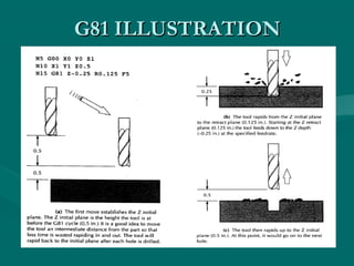
  • 29. The sequence of some machining operations is may be the same for any part and for any machine. For example, drilling a hole involves the following steps: Position the tool above the point where the hole will be drilled Set the correct spindle speed Feed the tool into the workpiece at a controlled feed rate to a predetermined depth Retract the tool at a rapid rate to just above the point where the hole started Canned Cycles
  • 30. Some Commonly Used Canned Cycle Code Function Down feed At bottom Retracti on G81 Drilling Continuous feed No action Rapid G82 Spot face, counterbore Continuous feed Dwell Rapid G83 Deep hole drilling Peck No action Rapid G84 Tapping Continuous feed Reverse spindle Feed rate G85 Through boring(in & out) Continuous feed No action Feed rate G86 Through boring(in only) Continuous feed Stop spindle Rapid
  • 32. Three Main parts of a CNC programThree Main parts of a CNC program • N5 G90 G2N5 G90 G211 (Absolute units,(Absolute units, metricmetric)) • N10 M06 T2N10 M06 T2 (Stop for tool change, use(Stop for tool change, use tool # 2)tool # 2) • N15 M03 S1200N15 M03 S1200 (Turn the spindle on CW(Turn the spindle on CW toto 1200 rpm)1200 rpm) Part 1- Program PetupPart 1- Program Petup
  • 33. Three Main parts of a CNC programThree Main parts of a CNC program • N20 G00 X1 Y1N20 G00 X1 Y1 (Rapid to X1,Y1 from origin(Rapid to X1,Y1 from origin point)point) • N25 Z0.125N25 Z0.125 (Rapid down to Z0.125)(Rapid down to Z0.125) • N30 G01 Z-0.125 FN30 G01 Z-0.125 F100100 (Feed down to Z-0.125 at(Feed down to Z-0.125 at 100 mm/100 mm/mminin)) • N35 G01 X2 Y2N35 G01 X2 Y2 (Feed diagonally to X2,Y2)(Feed diagonally to X2,Y2) • N40 G00 Z1N40 G00 Z1 (Rapid up to Z1)(Rapid up to Z1) • N45 X0 Y0N45 X0 Y0 (Rapid to X0,Y0)(Rapid to X0,Y0) Part 2- Chip RemovalPart 2- Chip Removal
  • 34. Three Main parts of a CNC programThree Main parts of a CNC program • N50 M05N50 M05 (Turn the spindle off)(Turn the spindle off) • N55 MN55 M0000 ((PProgramrogram stopstop)) Part 3- System ShutdownPart 3- System Shutdown
  • 35. EXAMPLE OPERATION on CNCEXAMPLE OPERATION on CNC MILLING MACHINEMILLING MACHINE
  • 36. G-CODE PROGRAMG-CODE PROGRAM • First pass : conventional mill to a depth of 0.125 around edge profile. Tool 1 is a ½ inch dia. end mill. % :1002 N5 G90 G20 N10 M06 T1 N15 M03 S1200 N20 G00 X0.125 Y0.125 N30 Z0.125 N35 G01 Z-0.125 F5 N40 X3.875 N45 Y4.125 N50 X0.125 N55 Y0.125
  • 37. • Second pass: conventional mill to a depth of 0.25 around edge profile. N35 Z-0.250 N40 X3.875 N45 Y4.125 N50 X0.125 N55 Y0.125 N60 Z0.125
  • 38. • Third pass: conventional mill to a depth of 0.125 around pocket profile. N65 G00 X1.25 Y1.0 N70 G01 Z-0.125 F5 N75 X1.75 N80 Y2.5 N85 X1.25 N90 Y1.0 N95 Z0.125
  • 39. • Fourth pass: climb mill to a depth of 0.125 across remaining material. N100 Y2.125 N105 X2.625 N110 Z0.125 N115 G00 X-5 Y-5 Z5 N120 M05 N125 M30
  • 40. Advanced features:Advanced features: • Execution of the part of the program in a rotatedExecution of the part of the program in a rotated or mirrored position.or mirrored position. • Ability to scale the program and produce larger orAbility to scale the program and produce larger or smaller programs.smaller programs. • Three dimensional circular interpolation whichThree dimensional circular interpolation which produces a helical shape.produces a helical shape. • Parabolic and cubic interpolation.Parabolic and cubic interpolation.
  • 41. • NC program preparation may be tedious and difficultNC program preparation may be tedious and difficult if the part to be machined has a complex geometry.if the part to be machined has a complex geometry. The main difficulty is to find out the cutter locationsThe main difficulty is to find out the cutter locations during the machining. Computers may be used toduring the machining. Computers may be used to assist the programmers in preparing the NC codes.assist the programmers in preparing the NC codes. Computer Aided Part Programming:
  • 42. Advantages of applying computer-aided partAdvantages of applying computer-aided part programming include the following:programming include the following: • 1. It reduces the manual calculations involves in1. It reduces the manual calculations involves in determining the geometric characteristics of the part.determining the geometric characteristics of the part. • It provides the cutter path simulation.It provides the cutter path simulation. • It provides tool collision checking.It provides tool collision checking. • It shortens the program preparation time.It shortens the program preparation time. • It makes the program preparation easier.It makes the program preparation easier.
  • 43. • The Aerospace Industries Association sponsored theThe Aerospace Industries Association sponsored the work that led to the first part programming language,work that led to the first part programming language, developed in MIT in 1955.developed in MIT in 1955. • This was called:This was called: Automatically Programmed ToolsAutomatically Programmed Tools (APT).(APT). • APT is an English like simple programming languageAPT is an English like simple programming language which basically produce thewhich basically produce the Cutter LocationCutter Location (CL) data.(CL) data. • Using the cutter location data, the program canUsing the cutter location data, the program can generate the actual NC codes by using agenerate the actual NC codes by using a postprocessor .postprocessor .
  • 44. • The output of any CAD package include theThe output of any CAD package include the geometric data of the part to be machined. Therefore,geometric data of the part to be machined. Therefore, many CAD/CAM package can produce cuttermany CAD/CAM package can produce cutter location (CL) data to be used for NC code generation.location (CL) data to be used for NC code generation. • There is still to be a process planning module for aThere is still to be a process planning module for a workable NC code generation.workable NC code generation. • Some of the CAD/CAM packages that have the NCSome of the CAD/CAM packages that have the NC code generation capabilities are Computervision,code generation capabilities are Computervision, CATIA, CADAM, ProEngineer, MechanicalDesktopCATIA, CADAM, ProEngineer, MechanicalDesktop (Auto Desk).(Auto Desk). CAD/CAM Based Part Programming:CAD/CAM Based Part Programming: