


Computer Architecture and Organization- arithmetic
- 1. ARITHMETIC
- 2. UNIT II ARITHMETIC 9 Fixed point Addition, Subtraction, Multiplication and Division. Floating Point arithmetic, High performance arithmetic, Subword parallelism Out come To familiarize with implementation of fixed point and floating- point arithmetic operations
- 3. Number System- Basics • Decimal number system Ten digits : 0, 1, 2, 3……9 -every digit position has a weight which is a power of 10 -Base or radix is 10 Example 234 =2x 10² + 3x101 + 4x 100 257.45 = 2x 10² + 5x101 + 7x 100 + 0.4x10⁻¹ +0.5x 10⁻² • Binary number system Two digits 0 and 1 -every digit position has a weight which is a power of 2 -Base or radix is 2 Example 110 = 1x 22 + 1x21 + 0x 20 101.01 = 1x 22 + 0x21 + 1x 20 + 0 x 2-1 +1x 10⁻²
- 4. Division Remainder (R) 112 / 2 = 56 0 56 / 2 = 28 0 28 / 2 = 14 0 14 / 2 = 7 0 7 / 2 = 3 1 3 / 2 = 1 1 1 / 2 = 0 1 • Decimal to Binary conversion Ans : (112)2 = (1110000)2 Convert decimal number 112 into binary number Example 1 Decimal fractional number 0.8125 into binary number. Example 2
- 5. • Binary to decimal conversion Example 1 Example 2 Example 3
- 6. Hexadecimal Number system A compact way to represent binary numbers -Group of four binary digits are represented by a hexadecimal digit -Hexa decimal degits are 0 to 9, Ato F
- 7. Binary to Hexadecimal Hexadecimal to binary
- 8. Representation of numbers 1. Sign magnitude representation -Positive numbers are represented as sign magnitude form range : -(2n-1 -1) to + (2n -1 -1) For n=4, range: -(23 -1) to + (23 -1) -7 to +7 1000 -0 1001 -1 1010 -2 1011 -3 1100 -4 1101 -5 1110 -6 1111 -7 0000 +0 0001 +1 0010 +2 0011 +3 0100 +4 0101 +5 0110 +6 0111 +7 Different representation for +0 and -0 • Unsigned integers - n bit number has 2n distinct combinations For n=3 , 23 =8 combinations 000, 001, 010, 011, 100, 101, 110,111 • Signed integers -Positive or negative number Three possible methods of representation 1. Sign magnitude representation 2. 1’s compliment representation 3. 2’s compliment representation
- 9. 2. 1’s compliment representation -Negative numbers are represented as 1’s complement form 1000 --- -7 1001 --- -6 1010 --- -5 1011 --- -4 1100 --- -3 1101 --- -2 1110 --- -1 1111 --- -0 Invert all bits. Each 1 becomes a 0 and 0 becomes 1 0000 --- +0 0001 --- +1 0010 --- +2 0011 --- +3 0100 --- +4 0101 --- +5 0110 --- +6 0011---- +7 Example, n=4 +4 = 0100 -4 = 1’s complement of 0100 = 1011 1000 --- -8 1001 --- -7 1010 --- -6 1011 --- -5 1100 --- -4 1101 --- -3 1110 --- -2 1111 --- -1 +4 = 0100 -4 = 2’s complement of 0100 = 1011+1 = 1100 0000 --- +0 0001 --- +1 0010 --- +2 0011 --- +3 0100 --- +4 0101 --- +5 0110 --- +6 0011---- +7 2’s compliment representation Computation of 2’s complement – Perform 1’s Complement - then add one to the resulting number.
- 10. • This representation has fixed number of bits for integer part and for fractional part. Fixed-Point Representation − three parts of a fixed-point number representation: the sign field, integer field, and fractional field. Example 32-bit format - 1 bit for the sign, 15 bits for the integer part ,16 bits for the fractional part. -43.625 is represented as 15 bits 16 bits 1 bit radix point (separator between integer and fractional parts)
- 11. -two part: first part - a signed fixed point number called mantissa. second - the position of the decimal (or binary) point and is called the exponent. 1 bit 8 bits 23 bits -53.5=(-110101.1)2=(-1.101011)x25 Example 3: Floating-Point Representation -scientific notation
- 12. Representation of Characters 1.Extended Binary Coded Decimal Interchange Code (EBCDIC) -Used in older IBM machines. 2. American Standard Code for Information Interchange (ASCII) - Most widely used today. 3. UNICODE - Used to represent all international characters. - Used by Java
- 13. UNIT II
- 14. Fixed Point Arithmetic 1. Addition 2. Subtraction 3. Multiplication 4. Division
- 15. Binary Addition adding 6ten to 7ten in binary Fixed point Addition Binary addition, sum and carries. carries are shown in parentheses
- 16. Subtracting 6ten from 7ten Binary Subtraction Fixed point Subtraction
- 17. Subtraction via addition using the 1’s complement
- 18. Example 1: 6 - 2 binary of 2 = 0010 1’s complement of 2 =1101 6 : 0110 -2 : 1101 1 00 11 1 0100 = +4 Consider 4 bit representation Carry is added back to the result Result is positive Example 2 : 3 - 5 binary of 2 = 0101 1’s complement of 5 =1010 3 : 0011 -5 : 1010 11 01 = -2 No Carry is added back to the result Result is positive
- 19. Subtraction via addition using the two’s complement
- 20. Example 1 : 6-2 Example 2: 3- 5
- 21. two’s complement of binary number- Simply invert every 0 to 1 and every 1 to 0, then add one to the result Subtracting 6ten from 7ten using 2’s compliment method Example 3
- 22. Overflow conditions for addition and subtraction ■Add (add), add immediate (addi), and subtract (sub) cause exceptions on overflow. ■ Add unsigned (addu), add immediate unsigned (addiu), and subtract unsigned (subu) do not cause exceptions on overflow.
- 23. exception, also called an (interrupt) - An exception is an event that occurs during the execution of a program that disrupts the normal flow of instructions. eg. divide by zero -The address of the instruction that overflowed is saved in a register, and the computer jumps to a predefined address to invoke the appropriate routine for that exception. Hardware that performs addition and subtraction, is called an Arithmetic Logic Unit(ALU) Exception program counter (EPC) -contain the address of the instruction that caused the exception.
- 24. Multiplying 1000ten by 1001ten For n-bit multiplicand , m-bit multiplier = product that is n + m bits long 1. Place a copy of the multiplicand (1 multiplicand) in the proper place if the multiplier digit is a 1, or 2. Place 0 (0 multiplicand) in the proper place if the digit is 0. Fixed point Multiplication
- 25. Multiplication hardware -- 64 bits Multiplier register - 32 bits. algorithm starts with the product register initialized to 0 32-bit multiplicand (right half of the Multiplicand register) is shifted left 1 bit on each step. multiplier is shifted in the opposite direction at each step Control decides when to shift the Multiplicand and Multiplier registers and when to write new values into the Product register.
- 26. Multiplication algorithm Multiplier register , Product register are initialized to 0 Multiplicand register, initialized with the 32-bit multiplicand in the right half and zero in the left half
- 27. Three steps in algorithm 1. LSB of the multiplier (Multiplier0) is checked If LSB = 1, multiplicand is added to the Product register. 2. Shift the multiplicand register to one bit left 3. shift the next bit of the multiplier register to right and check for iteration Three steps are repeated 32 times to obtain the product Multiply can take multiple clock cycles without significantly improving the performance The ALU is twice as wide as necessary The multiplicand register takes twice as many bits as needed The product register won’t need 2n bits till the last step The multiplier register is being emptied during the process Drawbacks
- 28. -- 32 bits product register - 64 bits. product register is shifted right No separate Multiplier register multiplier is placed in the right half of the Product register Refined version of the multiplication hardware
- 29. Example multiply 2ten x 3ten, or 0010two x 0011two.
- 30. one 32-bit adder for each bit of the multiplier: - one input is the multiplicand ANDed with a multiplier bit, and the other is the output of a prior adder. Connect the outputs of adders on the right to the inputs of adders on the left , making a stack of adders faster than five add times because of the use of carry save adders Faster Multiplication MIPS provides a separate pair of 32-bit registers to contain the 64-bit product, called Hi and Lo. Multiply in MIPS
- 31. • long division using decimal numbers divide 10010102 by 10002 Dividend Quotient x Divisor + Remainder Division two operands, called the dividend and divisor the result, called the quotient, a second result, called the remainder
- 32. -- 64 bits Quotient register - 32 bits. 32-bit Quotient register set to 0. 32-bit divisor starts in the left half of the Divisor register and is shifted to right by 1 bit for each iteration. Remainder is initialized with the dividend. Control decides when to shift the Divisor and Quotient registers and when to write the new value into the Remainder register. Division Hardware
- 34. 1. subtract the divisor register from remainder register 2. If the difference is positive, generate a 1 in the quotient (the divisor was smaller or equal to the dividend) -If the result is negative, restore the original value by adding the divisor back to the remainder and generate a 0 in the quotient 3. The divisor is shifted right and iterate again. The remainder and quotient will be found in the respective registers after all iterations are completed Three steps in algorithm
- 35. Dividing 7ten by 2ten or 0000 0111two by 0010two Example
- 36. ALU and Divisor registers are halved and the remainder is shifted left . Quotient register is combined the with the right half of the Remainder register. Improved version of the division hardware -- 32 bits Remainder register - 64 bits.
- 37. Signed Division Dividend = Quotient x Divisor + Remainder signs of the operands are opposite----negates the quotient sign of the remainder match the dividend signs of the operands are same------- quotient is positive sign of the remainder match the dividend Faster Division SRT division technique- -produce more than one bit of the quotient per step -using a table lookup based on the upper bits of the dividend and remainder Divide in MIPS 32-bit Hi and 32-bit Lo registers for both multiply and divide. MIPS instructions -- divide (div) and divide unsigned (divu) mflo or mfhi instructions – to place the desired result into a general-purpose register
- 38. Floating Point 0.000000001ten or 1.0ten × 10−9 3,155,760,000ten or 3.15576ten × 109 Allows for a varying number of digits before and after the decimal point scientific notation(single digit to the left of the decimal point) A number in scientific notation that has no leading 0s is called a normalized number
- 39. Floating-Point Representation Floating point number consists of two part: - a signed fixed point number in the fraction field called mantissa(significand) - the position of the decimal (or binary) point is called the exponent. General form of floating-point numbers is Fraction(F) lies between 2.0ten x 10-38 to 2.0ten x 1038 single precision floating point-IEEE 754 Overflow -positive exponent becomes too large to fit in the exponent field. underflow – negative exponent becomes too large to fi t in the exponent field. s -sign
- 40. Double precision floating point -IEEE 754 • has a larger exponent to reduce chances of underflow or overflow 11-bit exponent field 52-bit fraction field. Fraction(F) lies between 2.0ten x 10-308 to 2.0ten x 10308 greater precision because of larger fraction. leading 1-bit of normalized binary numbers implicit In single precision(F=24 bit) - implied 1 and a 23-bit fraction In double precision(F= 53 bits) - (1 + 52) General form of floating-point numbers is
- 41. features of IEEE 754 special symbols to represent unusual events ∞ or ∞-for largest exponent NaN- for Not a Number -0/0 or subtracting ∞ from ∞ 16-bit format (“half precision”) and a 128-bit format (“quadruple precision”). Bias Exponent -1 is represented as -1 + 127 = 126 = 011111102 bias of single precision is 127 double precision is 1023 +1 is represented as +1 + 127 = 128 = 100000002 With biased exponent, the floating- point number(IEEE 754 floating point format) is
- 42. IEEE 754 binary representation of the number - 0.75ten in single and double precision. Example 1: binary representation of- 0.75ten = 0.11two scientific notation = 0.11two x 20 normalized scientific notation = 1.1two x 2-1 Converting Decimal to Binary Floating Point double precision representation bias is 127 , exponent of 1.1two x 2-1 is represented as -1+127 =126= 011111102 Single precision representation bias is 1023 , exponent of 1.1two x 2-1 is represented as -1+1023 =1022= 011111111102
- 43. Converting Binary to Decimal Floating Point Example 2: What decimal number is represented by this single precision float? sign bit - 1, exponent field - 129 fraction field - 1x2-2 = 1/4, or 0.25. Solution General representation for a single precision number Con.expo=original exp +127
- 44. Floating Point Arithmetic 1. Floating Point Addition Decimal Binary 2. Floating Point Multiplication Decimal Binary
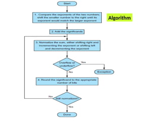
- 45. 1.Floating Point Addition Step 1 Align decimal points - Shifts the significand of the smaller number to the right until its exponent matches that of the larger number Step 2 Add the significands Smallest Assume 4 digits of the significand and 2 digits for exponent Decimal
- 46. Step 3 Normalized the result by adjusting the exponent appropriately and check for over/underflow Step 4 Round and renormalize if necessary Normalization of (four digits in the significand)
- 47. Binary Floating-Point Addition Step 1 Align decimal points - Shifts the significand of the smaller number to the right until its exponent matches the exponent of the larger number Step 2 Add the significands assume 4 bits of precision adding the numbers 0.5ten and 0.4375ten in binary 2’s complement of 0.111two = 001tw
- 48. Step 3 Normalized the result by adjusting the exponent appropriately and check for over/underflow depends on the precision of the operands Since 127 > -4 > - 126, there is no overflow or underflow biased exponent is - 4 + 127 = 123(between 1 and 254) Step 4 Round and renormalize if necessary
- 49. Algorithm
- 50. Arithmetic unit for floating-point addition
- 51. 1. exponent of one operand is subtracted from the other using the small ALU 2. difference controls the three multiplexors a. select the larger exponent b. significand of the smaller number c. significand of the larger number 3. smaller significand is shifted right 4. The significands are added together using the big ALU 5. normalization step shifts the sum left or right and increments or decrements the exponent 6. Rounding and creates the final result, which may require normalizing again to produce the actual final result.
- 52. 2. Floating Point Multiplication multiplying decimal numbers in scientific notation : 1.110ten x1010 and 9.200ten x10-5 . Step 1 Calculate the exponent of the product Step 2 Multiplication of significands Exponent of product = 10 +(-5) = 5 With bias, product exponent is 137 (10+127)+ 122 (-5+127)= 259 decimal point is placed six digits from the right(three digits for each operand) Ans = a. Decimal
- 53. Step 3 Normalized the result by adjusting the exponent appropriately and check for over/underflow depends on the precision of the operands product can be shifted right one digit Step 4 Round and renormalize if necessary is rounded to (only four digits long) Step 5 Determine sign of the product from signs of operands If both are same, the sign is positive; otherwise, it’s negative
- 54. Algorithm
- 55. b. Binary multiplying the numbers 0.5ten and - 0.4375ten Step 1. Adding the exponents without bias: biased representation 126(-1+127) +125(-2+127) = 251 It is too large. Therefore subtract 127 from this. 251-127= 124 Step 2. Multiplying the significands: product is = In binary
- 56. Step 3. Normalized, and check the exponent for overflow or underflow Normalized product : no overflow or underflow Also, , exponent fits Step 4. Rounding the product : ( four digit) Step 5. Determine sign of the product from signs of operands Since the signs of the operands are different, sign of the product is negative Product is Converting to decimal = -(0x2-1 +0x2-2 +1x2-3 +1x2-4 +1x2-5 +0x2-6 ) = -(0x1/2+0x1/22 +1x1/23 +1x1/24 +1x1/25 ) = -(0+0+ 0.125 +0.0625 + 0.03125) = -0.21875ten
- 57. • MIPS supports the IEEE 754 (single precision and double precision) formats Floating-Point Instructions in MIPS ■ Floating-point addition - single precision(add.s) , double precision (add.d) ■ Floating-point subtraction - single (sub.s) , double (sub.d) ■ Floating-point multiplication-single (mul.s) , double (mul.d) ■ Floating-point division - single (div.s) , double (div.d) ■ Floating-point comparison- single (c.x.s) , double (c.x.d), x may be equal (eq), not equal (neq), less than (lt), less than or equal(le), greater than (gt), or greater than or equal (ge) ■ Floating-point branch - true (bc1t), false (bc1f) Separate floating-point registers — 32 single-precision: $f0, $f1, … $f31 -Paired for double-precision: $f0/$f1, $f2/$f3, … even/odd even(name) - odd-numbered floating-point registers are used only to load and store the right half of 64-bit floating-point numbers -single instruction results in two parallel floating-point operations
- 58. Example FP instructions operate only on FP registers FP load and store instructions – lwc1, ldc1, swc1, sdc1
- 61. guard and round IEEE 754, always keeps two extra bits on the right during intermediate additions, called guard and round so that the rounding takes place in the final step sticky bit it is set whenever there are nonzero bits to the right of the round bit.
- 62. High performance Arithmetic speed, power and chip area are the most often used measures of the efficiency of an algorithm 1. Booth algorithm 2. Carry look ahead adder Improve the speed of arithmetic operation
- 63. reduce the number of partial products, speed up the multiplication process. used for both sign-magnitude numbers as well as 2's complement numbers Booth's algorithm Convert the multiplicand and multiplier into two’s complement of X bit x- at least one bit greater than the binary representation of larger operand Multiply (-5)10 and (2)10 Convert to binary (-5)10 -11011(Multiplier) (2)10 00010(Multiplicand) Get the beginning product -Add N leading zeros to N bit multiplier 00000 11011 For the first phase, 0 is the previous LSB N bit multiplier has N phases in Booths algorithm N=5, Therefore 5 phases Procedure
- 64. Use LSB and previous LSB to determine the arithmetic action in each phase Initial product and previous LSB is 00000 11011 0 Possible arithmetic actions 00 → no arithmetic operation 01 → add multiplicand to left half of the product 10 → subtract multiplicand from left half of the product 11 → no arithmetic operation Step 2: perform arithmetic right shift(ASR) on the entire product Step 1: Examine the last two bits and perform arithmetic 00000 11011 0 00000 (Left half of the product) - 00010 (multiplicand) 11110 Place the result into left half of product 11110 11011 0 Before ASR 11110 11011 0 After ASR 11111 01101 1 Phase 1 Phase 2 Step 1: Examine the last two bits and perform arithmetic 11111 01101 1 No arithmetic operation Before ASR 1111 01101 1 After ASR 1111 10110 1
- 65. Phase 3 Step 1: Examine the last two bits and perform arithmetic 1111 10110 1 Step 2: perform arithmetic right shift(ASR) on the entire product Place the result into left half of product 00001 10110 1 00000 11011 0 Phase 4 Step 1: Examine the last two bits 00000 11011 0 00000 - 00010 11110 Place the result into left half of product 11110 11011 0 11111 + 00010 1 00001 (discard carry) Step 2: perform arithmetic right shift(ASR) on the entire product 11110 11011 0 After ASR 11111 01101 1 11111 01101 1 Before ASR Phase 5 Step 1: Examine the last two bits 11111 01101 1 Step 2: perform arithmetic right shift(ASR) on the entire product 11111 01101 1 Before ASR After ASR 11111 10110 1 No operation
- 67. Example 2 Multiply 0010 x 1101 (2 x -3)
- 68. A carry-lookahead adder (CLA) or fast adder is a type of adder used in digital logic. improves speed by reducing the amount of time required to determine carry bits The carry-lookahead adder calculates one or more carry bits before the sum, Reduces the carry propagation delay Carry-lookahead adder (CLA)
- 69. carry-lookahead adder It is based on the fact that a carry signal will be generated in two cases: (1) when both bits Ai and Bi are 1, or (2) when one of the two bits is 1 and the carry-in (carry of the previous stage) is 1. Each full adder generate sum Si, carry propagate signal Pi and carry generate signal Gi
- 70. Full adder circuit with carry generate and carry propagate signals Truth table
- 71. Boolean expression for carry generate and propagate signal
- 72. Subword Parallelism(data level parallelism) In subword parallelism, multiple subwords are packed into a word and then process whole words. this technique results in parallel processing of subwords Since the same instruction is applied to all subwords within the word, this is a form of SIMD(Single Instruction Multiple Data) processing graphics systems use 8 bits to represent images. Audio samples need 16 bits. 128 bit word- sixteen 8-bit operands, eight 16-bit operands, four 32-bit operands, or two 64-bit operands For example if word size is 64bits and subwords sizes are 8,16 and 32 bits. Hence an instruction operates on eight 8bit subwords, four 16bit subwords, two 32bit subwords or one 64bit subword in parallel.
- 73. Application · Subword parallelism is an efficient and flexible solution for media processing because algorithm exhibit a great deal of data parallelism on lower precision data. It is also useful for computations unrelated to multimedia that exhibit data parallelism on lower precision data.