SlideShare a Scribd company logo
Lecture 3: Line Coding
Line Coding
• Line Coding is a pattern of Voltage, Current
or photons used to represent digital data
transmitted down a communication channel
or written to a storage medium.
• Converting a string of 1’s and 0’s (digital
data) into a sequence of signals that denote
the 1’s and 0’s.
• For example a high voltage level (+V) could
represent a “1” and a low voltage level (0 or
-V) could represent a “0”.
• Various Conversion techniques used
DATA SIGNAL APPROACH
Digital Digital Encoding
Analog Digital Encoding
Analog Analog Modulation
Digital Analog Modulation
The type of signal to be used depends on the
Situation and the available Bandwidth
DIGITAL DATA – DIGITAL SIGNAL
• Digital data is converted to digital signal for transmission.
• Line coding is the technique used to convert digital data into digital signal.
• We assume that data, in the form of text, numbers, graphical images,
audio, or video, are stored in computer memory as sequences of bits.
Line coding and decoding
Mapping Data symbols onto
Signal levels
• A data symbol (or element) can consist of a
number of data bits:
– 1 , 0 or
– 11, 10, 01, ……
• A data symbol can be coded into a single signal
element or multiple signal elements
– 1 -> +V, 0 -> -V
– 1 -> +V and -V, 0 -> -V and +V
• The ratio ‘r’ is the number of data elements
carried by a signal element.
Signal Element Versus Data Element
• In data communications, our goal is to send data elements.
• A data element is the smallest entity that can represent a
piece of information: this is the bit.
• In digital data communications, a signal element carries data
elements.
• A signal element is the shortest unit of a digital signal.
• In other words, data elements are what we need to send;
signal elements are what we can send.
• Data elements are being carried; signal elements are the
carriers
Signal element versus data element
We define a ratio r which is the number of data elements carried by each signal
element. Figure below shows several situations with different values of r.
Data Rate Versus Signal Rate The data rate defines the number of data elements
(bits) sent in 1s. The unit is bits per second (bps). The signal rate is the number of
signal elements sent in 1s. The unit is the baud. The data rate is sometimes called
the bit rate; the signal rate is sometimes called the pulse rate, the modulation rate,
or the baud rate.
A signal is carrying data in which one data element is
encoded as one signal element ( r = 1). If the bit rate
is 100 kbps, what is the average value of the baud rate
if c is between 0 and 1?
Solution
We assume that the average value of c is 1/2 . The baud
rate is then
Example 1
We now need to consider the relationship between data rate and signal
rate (bit rate and baud rate). This relationship, of course, depends on the
value of r. It also depends on the data pattern C. If we have a data pattern
of all 1 s or all Os, the signal rate may be different from a data pattern of
alternating Os and 1 s.
where N is the data rate (bps); c is the case
factor, which varies for each case; S is the
number of signal elements; and r is the
previously defined factor
Although the actual bandwidth of a digital signal is
infinite, the effective bandwidth is finite.
we can say that the bandwidth (range of frequencies) is proportional to the signal
rate (baud rate). The minimum bandwidth can be given as
We can solve for the maximum data rate if the bandwidth of the channel is given.
Example 2
The maximum data rate of a channel is Nmax = 2 × B × log2 L (defined
by the Nyquist formula). Does this agree with the previous formula for
Nmax?
Solution
A signal with L levels actually can carry log2L bits per level. If each level corresponds to
one signal element and we assume the average case (c = 1/2), then we have
Important Characteristics of Line
Coding
• Number of signal levels
• Bit rate and Baud rate
• DC components
• Signal Spectrum
• Noise Immunity
• Error Detection
• Synchronization and
• Cost of Implementation
Baseline Wandering: In decoding a digital signal, the receiver calculates
a running average of the received signal power. This average is called the baseline.
The incoming signal power is evaluated against this baseline to determine the value
of the data element.
A long string of 0s or 1 s can cause a drift in the baseline (baseline wandering) and
make it difficult for the receiver to decode correctly.
A good line coding scheme needs to prevent baseline wandering.
DC Components: When the voltage level in a digital signal is constant for a
while, the spectrum creates very low frequencies .
These frequencies around zero, called DC (direct-current) components, present
problems for a system that cannot pass low frequencies or a system that uses
electrical coupling (via a transformer).
For example, a telephone line cannot pass frequencies below 200 Hz. Also a long-
distance link may use one or more transformers to isolate different parts of the line
electrically. For these systems, we need a scheme with no DC component.
Self-synchronization: To correctly interpret the signals received from the
sender, the receiver's bit intervals must correspond exactly to the sender's bit
intervals. If the receiver clock is faster or slower, the bit intervals are not matched
and the receiver might misinterpret the signals.
Figure 4.3 Effect of lack of synchronization
A self-synchronizing digital signal includes timing information in
the data being transmitted. This can be achieved if there are
transitions in the signal that alert the receiver to the beginning,
middle, or end of the pulse. If the receiver' s clock is out of
synchronization, these points can reset the clock.
In a digital transmission, the receiver clock is 0.1
percent faster than the sender clock. How many extra
bits per second does the receiver receive if the data
rate is 1 kbps? How many if the data rate is 1 Mbps?
Solution
At 1 kbps, the receiver receives 1001 bps instead of 1000
bps.
Example 3
At 1 Mbps, the receiver receives 1,001,000 bps
instead of 1,000,000 bps.
LINE CODING SCHEMES
Unipolar
• All signal levels are on one side of the time axis -
either above or below
• NRZ - Non Return to Zero scheme is an example of
this code. The signal level does not return to zero
during a symbol transmission.
• Scheme is prone to baseline wandering and DC
components. It has no synchronization or any
error detection. It is simple but costly in power
consumption.
Figure 5 Unipolar NRZ scheme
Unipolar Coding
Characteristics of Unipolar Coding
•It uses only one polarity of voltage level
•Bit rate same as data rate
•DC components present
•Loss of synchronization for long sequences of
0’s and 1’s
•Simple but Obsolete
Polar Coding
• Uses two voltage levels, One positive and the
other one negative
NRZ
Non-Return-to-Zero
•Voltage level is constant during a bit interval
•There are two NRZ schemes
I.NRZ – I
II.NRZ - L
NRZ – L
1 = Low Level
0 = High Level
NRZ - I
• For each 1 in the bit sequence, the signal level is inverted
• A transition from one voltage level to the other represents
a 1
Characteristics of NRZ
-Two Levels
-Bit rate same as Data
rate
-Loss of Synchronization
for long sequence of 0’s
or 1’s
Lecture notes eng  - Line Coding New.ppt
A system is using NRZ-I to transfer 1-Mbps
data. What are the average signal rate and
minimum bandwidth?
Solution
The average signal rate is S= c x N x R = 1/2 x N x 1 =
500 kbaud. The minimum bandwidth for this average
baud rate is Bmin = S = 500 kHz.
Note c = 1/2 for the avg. case as worst case is 1 and best
case is 0
Example
RZ
Return to Zero
• To ensure synchronization, there must be a
signal transition in each bit
Characteristics of RZ Encoding
• Three levels
• Bit rate is double that of data rate
• No DC component
• Good Synchronization
• Increase in bandwidth is the main limitation
Polar - Biphase: Manchester and
Differential Manchester
• Manchester coding consists of combining the
NRZ-L and RZ schemes.
– Every symbol has a level transition in the middle: from
high to low or low to high. Uses only two voltage levels.
• Differential Manchester coding consists of
combining the NRZ-I and RZ schemes.
– Every symbol has a level transition in the middle. But
the level at the beginning of the symbol is determined
by the symbol value. One symbol causes a level change
the other does not.
Polar biphase: Manchester and differential Manchester schemes
• In Manchester and differential Manchester encoding, the transition at the middle of
the bit is used for synchronization.
• The minimum bandwidth of Manchester and differential Manchester is 2 times that of NRZ.
The Manchester scheme overcomes several problems associated with NRZ-L, and
differential Manchester overcomes several problems associated with NRZ-I. First, there
is no baseline wandering. There is no DC component because each bit has a positive
and negative voltage contribution. The only drawback is the signal rate. The signal rate
for Manchester and differential Manchester is double that for NRZ. The reason is that
there is always one transition at the middle of the bit and maybe one transition at the
end of each bit.
Characteristics of Biphase Encoding
• Two levels
• No DC component
• Good Synchronization
• Higher bandwidth due to doubling of bit rate
with respect to data rate
BIPOLAR ENCODING
• AMI – Amplitude Mark Inversion
Bipolar AMI
• Uses three voltage levels
• Unlike RZ, the zero level is used to represent a 0
• Binary 1s are represented by alternatively
positive and negative voltage
Characteristics of Bipolar AMI
• Three levels
• No DC component
• Loss of synchronization for long sequence of 0’s
• Lesser Bandwidth
Pseudotenary – A coding scheme same as AMI, but
alternating positive and negative pulses occur for binary
0 instead of binary 1
Bipolar schemes: AMI and pseudoternary
In bipolar encoding (sometimes called multilevel binary), we use three levels:
positive, zero, and negative.
The bipolar scheme was developed as an alternative to NRZ.
The bipolar scheme has the same signal rate as NRZ, but there is no DC component.
The NRZ scheme has most of its energy concentrated near zero frequency, which
makes it unsuitable for transmission over channels with poor performance around
this frequency.
The concentration of the energy in bipolar encoding is around frequency N/2.
AMI used with scrambling
Biphase schemes that are suitable for dedicated links between stations in a LAN
are not suitable for long-distance communication because of their wide bandwidth
requirement.
If we can find a way to avoid a long sequence of Os in the original stream, we can
use bipolar AMI for long distances.
We are looking for a technique that does not increase the number of bits and does provide
synchronization.
We are looking for a solution that substitutes long zero-level pulses with a combination of
other levels to provide synchronization. One solution is called scrambling.
AMI used with scrambling
Special Purpose Codes
Scrambling Schemes
• Extensions of Bipolar AMI
• Used incase of long distance applications
• Goals
- No DC component
- No long sequence of 0-level line signal
- Minimum increase in bandwidth
- Error detection capability
- Examples B8ZS and HDB3
Bipolar Coding Schemes
B8ZS Scheme
• Bipolar with 8-Zero Substitution
• The limitation of bipolar AMI is overcome in B8ZS,
which is used in North America
• A sequence of eight zeros is replaced by the following
encoding
- A sequence of eight 0’s is replaced by 000+-0+-, if the
previous pulse was positive
- A sequence of eight 0’s is replaced by 000-+0+-, if the
previous pulse was negative
B8ZS
V = Bipolar Violation, B = Valid Bipolar
Violation
B8ZS
HDB3 Scheme
High Density Bipolar – 3 Zeros
• Another alternative, which is used in Europe and Japan
• It replaces a sequence of 4 zeros by a code as per the
rule given in the table below
HDB3
HDB3
-Examples B8ZS and HDB3
Characteristics of B8ZS and HDB3
• Three levels
• No DC component
• Good Synchronization
• most of the energy is concentrated around a
frequency equal to half the data rate
• Well suited for high data-rate transmission over
long distance
Spectrum Comparison
Ethernet Standards and Signaling
Individual Assignment
• Draw line codes for 1010 0000 0000 1011
0000 1011 0000
–RZ
–NRZ-L, NRZ-I
–AMI, Pseudoternary, HDB3, B8ZS,
–Manchester and differential
Manchester schemes
Thank You!
Ad

Recommended

line coding techniques, block coding and all type of coding
DrZMaryLivinsaProfEC
 
unit 2 intr to phy layer part 1.pptcvcvcv
zmulani8
 
Ch4 Data communication and networking by neha g. kurale
Neha Kurale
 
Unit 4
Unit 4
Srashti Vyas
 
lec5_13.pptx
lec5_13.pptx
ShakibAhmed52
 
Lecture 08
Lecture 08
Anwal Mirza
 
Data communications 4 1
Raymond Pidor
 
Multi level multi transition
Faculty of Engineering, Alexandria University, Egypt
 
ch04-digital-transmission.ppt
CDSukte
 
Computer network and its applications.pdf
m46928702
 
Computer network and its types application.pdf
m46928702
 
Lecture 08
Lecture 08
Sehrish Rafiq
 
Data Communication And Networking - DIGITAL TRANSMISSION
Avijeet Negel
 
Ch4 1 v1
Ch4 1 v1
bhagavanprasad
 
ch4_1_v1edit-1.pptjjjjjjjjjjjjjjjjjjjjjjjjjjjjjjkkkkkkkkkkkkkkkkkk
vijaykumar9346565338
 
ch4_1_v1edit-1.ppt digital transmission from pl
relief4u2004
 
Data Encoding in Data Communication.pptx
zulhelmanz
 
ch4_1_v1.pptwwwwwwwwwwwwwwwwwwwwwwwwwwwwwww
subhadipmalakar981
 
Unit-2-04-digitatoDogitalconversion.pptx
Shilpachaudhari10
 
Computer Networks/Computer Engineering.pdf
abdnazar2003
 
Lec-12-DCN.pptx about digital transmission and conversions
az577330
 
Components of data communication
Md Abdus Sobur Sikdar
 
base-band_digital_data_transmission-Line coding - Copy.ppt
AbyThomas54
 
CCN
CCN
NICE
 
DC MODULE 3 PPT from the data communicatiobs
treddy21
 
Chap4 d t-d conversion
arslan_akbar90
 
Signal encoding techniques
Syed Zaid Irshad
 
signalencodingtechniques-170203124858.pdf
alyaamohammed251
 
L1 General Introductionbbbbbbbbbb-1.pptx
JumanneChiyanda
 
In aumkokbvkhkGENERAL HV GENERATION.pptx
JumanneChiyanda
 

More Related Content

Similar to Lecture notes eng - Line Coding New.ppt (20)

ch04-digital-transmission.ppt
CDSukte
 
Computer network and its applications.pdf
m46928702
 
Computer network and its types application.pdf
m46928702
 
Lecture 08
Lecture 08
Sehrish Rafiq
 
Data Communication And Networking - DIGITAL TRANSMISSION
Avijeet Negel
 
Ch4 1 v1
Ch4 1 v1
bhagavanprasad
 
ch4_1_v1edit-1.pptjjjjjjjjjjjjjjjjjjjjjjjjjjjjjjkkkkkkkkkkkkkkkkkk
vijaykumar9346565338
 
ch4_1_v1edit-1.ppt digital transmission from pl
relief4u2004
 
Data Encoding in Data Communication.pptx
zulhelmanz
 
ch4_1_v1.pptwwwwwwwwwwwwwwwwwwwwwwwwwwwwwww
subhadipmalakar981
 
Unit-2-04-digitatoDogitalconversion.pptx
Shilpachaudhari10
 
Computer Networks/Computer Engineering.pdf
abdnazar2003
 
Lec-12-DCN.pptx about digital transmission and conversions
az577330
 
Components of data communication
Md Abdus Sobur Sikdar
 
base-band_digital_data_transmission-Line coding - Copy.ppt
AbyThomas54
 
CCN
CCN
NICE
 
DC MODULE 3 PPT from the data communicatiobs
treddy21
 
Chap4 d t-d conversion
arslan_akbar90
 
Signal encoding techniques
Syed Zaid Irshad
 
signalencodingtechniques-170203124858.pdf
alyaamohammed251
 
ch04-digital-transmission.ppt
CDSukte
 
Computer network and its applications.pdf
m46928702
 
Computer network and its types application.pdf
m46928702
 
Data Communication And Networking - DIGITAL TRANSMISSION
Avijeet Negel
 
ch4_1_v1edit-1.pptjjjjjjjjjjjjjjjjjjjjjjjjjjjjjjkkkkkkkkkkkkkkkkkk
vijaykumar9346565338
 
ch4_1_v1edit-1.ppt digital transmission from pl
relief4u2004
 
Data Encoding in Data Communication.pptx
zulhelmanz
 
ch4_1_v1.pptwwwwwwwwwwwwwwwwwwwwwwwwwwwwwww
subhadipmalakar981
 
Unit-2-04-digitatoDogitalconversion.pptx
Shilpachaudhari10
 
Computer Networks/Computer Engineering.pdf
abdnazar2003
 
Lec-12-DCN.pptx about digital transmission and conversions
az577330
 
base-band_digital_data_transmission-Line coding - Copy.ppt
AbyThomas54
 
CCN
CCN
NICE
 
DC MODULE 3 PPT from the data communicatiobs
treddy21
 
Chap4 d t-d conversion
arslan_akbar90
 
Signal encoding techniques
Syed Zaid Irshad
 
signalencodingtechniques-170203124858.pdf
alyaamohammed251
 

More from JumanneChiyanda (8)

L1 General Introductionbbbbbbbbbb-1.pptx
JumanneChiyanda
 
In aumkokbvkhkGENERAL HV GENERATION.pptx
JumanneChiyanda
 
Synchronous COUNTER presentation eng.ppt
JumanneChiyanda
 
A digital group 8 for presentations.pptx
JumanneChiyanda
 
interfacing1 lecture notes for eng 5.ppt
JumanneChiyanda
 
Three-Phase Alternating C MachinesL2.pptx
JumanneChiyanda
 
Array and string in C++_093547 analysis.pptx
JumanneChiyanda
 
NEW TRAINING ON E-RESOURCES ACCESS AND USE.ppt
JumanneChiyanda
 
Ad

Recently uploaded (20)

AI_Presentation (1). Artificial intelligence
RoselynKaur8thD34
 
Solar thermal – Flat plate and concentrating collectors .pptx
jdaniabraham1
 
20CE404-Soil Mechanics - Slide Share PPT
saravananr808639
 
Structured Programming with C++ :: Kjell Backman
Shabista Imam
 
تقرير عن التحليل الديناميكي لتدفق الهواء حول جناح.pdf
محمد قصص فتوتة
 
Complete University of Calculus :: 2nd edition
Shabista Imam
 
May 2025: Top 10 Read Articles in Data Mining & Knowledge Management Process
IJDKP
 
LECTURE 7 COMPUTATIONS OF LEVELING DATA APRIL 2025.pptx
rr22001247
 
Deep Learning for Natural Language Processing_FDP on 16 June 2025 MITS.pptx
resming1
 
Bitumen Emulsion by Dr Sangita Ex CRRI Delhi
grilcodes
 
Kel.3_A_Review_on_Internet_of_Things_for_Defense_v3.pptx
Endang Saefullah
 
Abraham Silberschatz-Operating System Concepts (9th,2012.12).pdf
Shabista Imam
 
Rapid Prototyping for XR: Lecture 6 - AI for Prototyping and Research Directi...
Mark Billinghurst
 
How to Un-Obsolete Your Legacy Keypad Design
Epec Engineered Technologies
 
Industry 4.o the fourth revolutionWeek-2.pptx
KNaveenKumarECE
 
International Journal of Advanced Information Technology (IJAIT)
ijait
 
Introduction to sensing and Week-1.pptx
KNaveenKumarECE
 
Introduction to Python Programming Language
merlinjohnsy
 
MATERIAL SCIENCE LECTURE NOTES FOR DIPLOMA STUDENTS
SAMEER VISHWAKARMA
 
Data Structures Module 3 Binary Trees Binary Search Trees Tree Traversals AVL...
resming1
 
AI_Presentation (1). Artificial intelligence
RoselynKaur8thD34
 
Solar thermal – Flat plate and concentrating collectors .pptx
jdaniabraham1
 
20CE404-Soil Mechanics - Slide Share PPT
saravananr808639
 
Structured Programming with C++ :: Kjell Backman
Shabista Imam
 
تقرير عن التحليل الديناميكي لتدفق الهواء حول جناح.pdf
محمد قصص فتوتة
 
Complete University of Calculus :: 2nd edition
Shabista Imam
 
May 2025: Top 10 Read Articles in Data Mining & Knowledge Management Process
IJDKP
 
LECTURE 7 COMPUTATIONS OF LEVELING DATA APRIL 2025.pptx
rr22001247
 
Deep Learning for Natural Language Processing_FDP on 16 June 2025 MITS.pptx
resming1
 
Bitumen Emulsion by Dr Sangita Ex CRRI Delhi
grilcodes
 
Kel.3_A_Review_on_Internet_of_Things_for_Defense_v3.pptx
Endang Saefullah
 
Abraham Silberschatz-Operating System Concepts (9th,2012.12).pdf
Shabista Imam
 
Rapid Prototyping for XR: Lecture 6 - AI for Prototyping and Research Directi...
Mark Billinghurst
 
Industry 4.o the fourth revolutionWeek-2.pptx
KNaveenKumarECE
 
International Journal of Advanced Information Technology (IJAIT)
ijait
 
Introduction to sensing and Week-1.pptx
KNaveenKumarECE
 
Introduction to Python Programming Language
merlinjohnsy
 
MATERIAL SCIENCE LECTURE NOTES FOR DIPLOMA STUDENTS
SAMEER VISHWAKARMA
 
Data Structures Module 3 Binary Trees Binary Search Trees Tree Traversals AVL...
resming1
 
Ad

Lecture notes eng - Line Coding New.ppt

  • 2. Line Coding • Line Coding is a pattern of Voltage, Current or photons used to represent digital data transmitted down a communication channel or written to a storage medium. • Converting a string of 1’s and 0’s (digital data) into a sequence of signals that denote the 1’s and 0’s. • For example a high voltage level (+V) could represent a “1” and a low voltage level (0 or -V) could represent a “0”.
  • 3. • Various Conversion techniques used DATA SIGNAL APPROACH Digital Digital Encoding Analog Digital Encoding Analog Analog Modulation Digital Analog Modulation The type of signal to be used depends on the Situation and the available Bandwidth
  • 4. DIGITAL DATA – DIGITAL SIGNAL • Digital data is converted to digital signal for transmission. • Line coding is the technique used to convert digital data into digital signal. • We assume that data, in the form of text, numbers, graphical images, audio, or video, are stored in computer memory as sequences of bits. Line coding and decoding
  • 5. Mapping Data symbols onto Signal levels • A data symbol (or element) can consist of a number of data bits: – 1 , 0 or – 11, 10, 01, …… • A data symbol can be coded into a single signal element or multiple signal elements – 1 -> +V, 0 -> -V – 1 -> +V and -V, 0 -> -V and +V • The ratio ‘r’ is the number of data elements carried by a signal element.
  • 6. Signal Element Versus Data Element • In data communications, our goal is to send data elements. • A data element is the smallest entity that can represent a piece of information: this is the bit. • In digital data communications, a signal element carries data elements. • A signal element is the shortest unit of a digital signal. • In other words, data elements are what we need to send; signal elements are what we can send. • Data elements are being carried; signal elements are the carriers
  • 7. Signal element versus data element We define a ratio r which is the number of data elements carried by each signal element. Figure below shows several situations with different values of r. Data Rate Versus Signal Rate The data rate defines the number of data elements (bits) sent in 1s. The unit is bits per second (bps). The signal rate is the number of signal elements sent in 1s. The unit is the baud. The data rate is sometimes called the bit rate; the signal rate is sometimes called the pulse rate, the modulation rate, or the baud rate.
  • 8. A signal is carrying data in which one data element is encoded as one signal element ( r = 1). If the bit rate is 100 kbps, what is the average value of the baud rate if c is between 0 and 1? Solution We assume that the average value of c is 1/2 . The baud rate is then Example 1 We now need to consider the relationship between data rate and signal rate (bit rate and baud rate). This relationship, of course, depends on the value of r. It also depends on the data pattern C. If we have a data pattern of all 1 s or all Os, the signal rate may be different from a data pattern of alternating Os and 1 s. where N is the data rate (bps); c is the case factor, which varies for each case; S is the number of signal elements; and r is the previously defined factor
  • 9. Although the actual bandwidth of a digital signal is infinite, the effective bandwidth is finite. we can say that the bandwidth (range of frequencies) is proportional to the signal rate (baud rate). The minimum bandwidth can be given as We can solve for the maximum data rate if the bandwidth of the channel is given. Example 2 The maximum data rate of a channel is Nmax = 2 × B × log2 L (defined by the Nyquist formula). Does this agree with the previous formula for Nmax? Solution A signal with L levels actually can carry log2L bits per level. If each level corresponds to one signal element and we assume the average case (c = 1/2), then we have
  • 10. Important Characteristics of Line Coding • Number of signal levels • Bit rate and Baud rate • DC components • Signal Spectrum • Noise Immunity • Error Detection • Synchronization and • Cost of Implementation
  • 11. Baseline Wandering: In decoding a digital signal, the receiver calculates a running average of the received signal power. This average is called the baseline. The incoming signal power is evaluated against this baseline to determine the value of the data element. A long string of 0s or 1 s can cause a drift in the baseline (baseline wandering) and make it difficult for the receiver to decode correctly. A good line coding scheme needs to prevent baseline wandering. DC Components: When the voltage level in a digital signal is constant for a while, the spectrum creates very low frequencies . These frequencies around zero, called DC (direct-current) components, present problems for a system that cannot pass low frequencies or a system that uses electrical coupling (via a transformer). For example, a telephone line cannot pass frequencies below 200 Hz. Also a long- distance link may use one or more transformers to isolate different parts of the line electrically. For these systems, we need a scheme with no DC component. Self-synchronization: To correctly interpret the signals received from the sender, the receiver's bit intervals must correspond exactly to the sender's bit intervals. If the receiver clock is faster or slower, the bit intervals are not matched and the receiver might misinterpret the signals.
  • 12. Figure 4.3 Effect of lack of synchronization A self-synchronizing digital signal includes timing information in the data being transmitted. This can be achieved if there are transitions in the signal that alert the receiver to the beginning, middle, or end of the pulse. If the receiver' s clock is out of synchronization, these points can reset the clock.
  • 13. In a digital transmission, the receiver clock is 0.1 percent faster than the sender clock. How many extra bits per second does the receiver receive if the data rate is 1 kbps? How many if the data rate is 1 Mbps? Solution At 1 kbps, the receiver receives 1001 bps instead of 1000 bps. Example 3 At 1 Mbps, the receiver receives 1,001,000 bps instead of 1,000,000 bps.
  • 15. Unipolar • All signal levels are on one side of the time axis - either above or below • NRZ - Non Return to Zero scheme is an example of this code. The signal level does not return to zero during a symbol transmission. • Scheme is prone to baseline wandering and DC components. It has no synchronization or any error detection. It is simple but costly in power consumption.
  • 16. Figure 5 Unipolar NRZ scheme
  • 17. Unipolar Coding Characteristics of Unipolar Coding •It uses only one polarity of voltage level •Bit rate same as data rate •DC components present •Loss of synchronization for long sequences of 0’s and 1’s •Simple but Obsolete
  • 18. Polar Coding • Uses two voltage levels, One positive and the other one negative
  • 19. NRZ Non-Return-to-Zero •Voltage level is constant during a bit interval •There are two NRZ schemes I.NRZ – I II.NRZ - L NRZ – L 1 = Low Level 0 = High Level
  • 20. NRZ - I • For each 1 in the bit sequence, the signal level is inverted • A transition from one voltage level to the other represents a 1 Characteristics of NRZ -Two Levels -Bit rate same as Data rate -Loss of Synchronization for long sequence of 0’s or 1’s
  • 22. A system is using NRZ-I to transfer 1-Mbps data. What are the average signal rate and minimum bandwidth? Solution The average signal rate is S= c x N x R = 1/2 x N x 1 = 500 kbaud. The minimum bandwidth for this average baud rate is Bmin = S = 500 kHz. Note c = 1/2 for the avg. case as worst case is 1 and best case is 0 Example
  • 23. RZ Return to Zero • To ensure synchronization, there must be a signal transition in each bit
  • 24. Characteristics of RZ Encoding • Three levels • Bit rate is double that of data rate • No DC component • Good Synchronization • Increase in bandwidth is the main limitation
  • 25. Polar - Biphase: Manchester and Differential Manchester • Manchester coding consists of combining the NRZ-L and RZ schemes. – Every symbol has a level transition in the middle: from high to low or low to high. Uses only two voltage levels. • Differential Manchester coding consists of combining the NRZ-I and RZ schemes. – Every symbol has a level transition in the middle. But the level at the beginning of the symbol is determined by the symbol value. One symbol causes a level change the other does not.
  • 26. Polar biphase: Manchester and differential Manchester schemes • In Manchester and differential Manchester encoding, the transition at the middle of the bit is used for synchronization. • The minimum bandwidth of Manchester and differential Manchester is 2 times that of NRZ. The Manchester scheme overcomes several problems associated with NRZ-L, and differential Manchester overcomes several problems associated with NRZ-I. First, there is no baseline wandering. There is no DC component because each bit has a positive and negative voltage contribution. The only drawback is the signal rate. The signal rate for Manchester and differential Manchester is double that for NRZ. The reason is that there is always one transition at the middle of the bit and maybe one transition at the end of each bit.
  • 27. Characteristics of Biphase Encoding • Two levels • No DC component • Good Synchronization • Higher bandwidth due to doubling of bit rate with respect to data rate
  • 28. BIPOLAR ENCODING • AMI – Amplitude Mark Inversion Bipolar AMI • Uses three voltage levels • Unlike RZ, the zero level is used to represent a 0 • Binary 1s are represented by alternatively positive and negative voltage
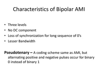
  • 29. Characteristics of Bipolar AMI • Three levels • No DC component • Loss of synchronization for long sequence of 0’s • Lesser Bandwidth Pseudotenary – A coding scheme same as AMI, but alternating positive and negative pulses occur for binary 0 instead of binary 1
  • 30. Bipolar schemes: AMI and pseudoternary In bipolar encoding (sometimes called multilevel binary), we use three levels: positive, zero, and negative. The bipolar scheme was developed as an alternative to NRZ. The bipolar scheme has the same signal rate as NRZ, but there is no DC component. The NRZ scheme has most of its energy concentrated near zero frequency, which makes it unsuitable for transmission over channels with poor performance around this frequency. The concentration of the energy in bipolar encoding is around frequency N/2.
  • 31. AMI used with scrambling Biphase schemes that are suitable for dedicated links between stations in a LAN are not suitable for long-distance communication because of their wide bandwidth requirement. If we can find a way to avoid a long sequence of Os in the original stream, we can use bipolar AMI for long distances. We are looking for a technique that does not increase the number of bits and does provide synchronization. We are looking for a solution that substitutes long zero-level pulses with a combination of other levels to provide synchronization. One solution is called scrambling. AMI used with scrambling
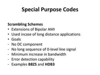
  • 32. Special Purpose Codes Scrambling Schemes • Extensions of Bipolar AMI • Used incase of long distance applications • Goals - No DC component - No long sequence of 0-level line signal - Minimum increase in bandwidth - Error detection capability - Examples B8ZS and HDB3
  • 34. B8ZS Scheme • Bipolar with 8-Zero Substitution • The limitation of bipolar AMI is overcome in B8ZS, which is used in North America • A sequence of eight zeros is replaced by the following encoding - A sequence of eight 0’s is replaced by 000+-0+-, if the previous pulse was positive - A sequence of eight 0’s is replaced by 000-+0+-, if the previous pulse was negative
  • 35. B8ZS V = Bipolar Violation, B = Valid Bipolar Violation
  • 36. B8ZS
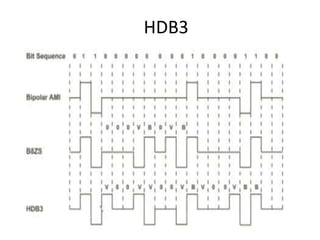
  • 37. HDB3 Scheme High Density Bipolar – 3 Zeros • Another alternative, which is used in Europe and Japan • It replaces a sequence of 4 zeros by a code as per the rule given in the table below
  • 38. HDB3
  • 39. HDB3
  • 41. Characteristics of B8ZS and HDB3 • Three levels • No DC component • Good Synchronization • most of the energy is concentrated around a frequency equal to half the data rate • Well suited for high data-rate transmission over long distance
  • 44. Individual Assignment • Draw line codes for 1010 0000 0000 1011 0000 1011 0000 –RZ –NRZ-L, NRZ-I –AMI, Pseudoternary, HDB3, B8ZS, –Manchester and differential Manchester schemes