SlideShare a Scribd company logo
5
Most read
11
Most read
13
Most read
DR. VIKAS J. DONGRE
HOD ELECTRONICS & TELECOM
GOVERNMENT POLYTECHNIC WASHIM (MS)
EMAIL: DONGREVJ1@GMAIL.COM
 The 8051 has two timers/counters, they can be
used either as
 Timers to generate a time delay or as
 Event counters to count events happening outside the
microcontroller
 Both Timer 0 and Timer 1 are 16 bits wide
 Since 8051 has an 8-bit architecture, each 16-bits timer is
accessed as two separate registers of low byte and high
byte
Timer programming for 8051 using embedded c
 Accessed as low byte and high byte
 The low byte register is called TL0/TL1 and
 The high byte register is called TH0/TH1
 Accessed like any other register
 MOV TL0,#4FH
 MOV R5,TH0
TH0 TL0
D15 D14 D13 D12 D11 D10 D9 D8 D7 D6 D5 D4 D3 D2 D1 D0
TH1 TL1
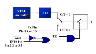
 Both timers 0 and 1 use the same register, called
TMOD (timer mode), to set the various timer operation modes
 TMOD is a 8-bit register
 The lower 4 bits are for Timer 0
 The upper 4 bits are for Timer 1
 In each case,
 The lower 2 bits are used to set the timer mode
 The upper 2 bits to specify the operation
(MSB) (LSB)
GATE C/T M1 M0
Timer1
GATE C/T M1 M0
Timer0
Timer programming for 8051 using embedded c
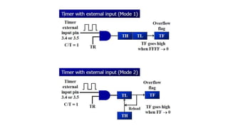
 The following are the characteristics and operations of mode1:
1. It is a 16-bit timer; therefore, it allows value of 0000 to FFFFH to be
loaded into the timer’s register TL and TH
2. After TH and TL are loaded with a 16-bit initial value, the timer must be
started
 This is done by SETB TR0 for timer 0 and SETB TR1 for timer 1
3. After the timer is started, it starts to count up
 It counts up until it reaches its limit of FFFFH
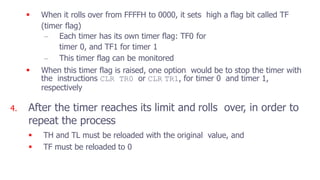
 When it rolls over from FFFFH to 0000, it sets high a flag bit called TF
(timer flag)
– Each timer has its own timer flag: TF0 for
timer 0, and TF1 for timer 1
– This timer flag can be monitored
 When this timer flag is raised, one option would be to stop the timer with
the instructions CLR TR0 or CLR TR1, for timer 0 and timer 1,
respectively
4. After the timer reaches its limit and rolls over, in order to
repeat the process
 TH and TL must be reloaded with the original value, and
 TF must be reloaded to 0
1. Load the TMOD value register indicating which timer
(timer 0 or timer 1) is to be used and which timer mode
(0 or 1) is selected
2. Load registers TL and TH with initial count value
3. Start the timer
4. Keep monitoring the timer flag (TF) with the JNB
TFx,target instruction to see if it is raised
 Get out of the loop when TF becomes high
5. Stop the timer
6. Clear the TF flag for the next round
7. Go back to Step 2 to load TH and TL again
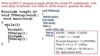
 To generate a time delay
#include <reg51.h>
void T0Delay(void);
void main(void)
{
while(1)
{
P1=0x55;
T0Delay();
P1=0xAA;
T0Delay();
}
}
void T0Delay()
{
TMOD=0x01;
TL0=0x00;
TH0=0x35;
TR0=1;
while (TF0==0);
TR0=0;
TF0=0;
}
FFFFH – 3500H = CAFFH
= 51967 + 1 = 51968
If crystal frequency= 11.0592MHz,
Then T=1/f, i.e. T= 1.085s
51968  1.085 s = 56.384 ms is
the approximate delay
Write an 8051 C program to toggle all the bits of port P1 continuously with
some delay in between. Use Timer 0, 16-bit mode to generate the delay.
Write an 8051 C program to create a frequency of 2500 Hz
on pin P2.7. Use Timer 1, mode 2 to create delay.
#include <reg51.h>
void T1M2Delay(void);
sbit mybit=P2^7;
void main(void)
{
unsigned char x;
while(1)
{
mybit=~mybit;
T1M2Delay();
}
}
void T1M2Delay(void)
{
TMOD=0x20;
TH1=-184;
TR1=1;
while (TF1==0);
TR1=0;
TF1=0;
}
1/2500 Hz = 400 s
400 s /2 = 200 s
200 s / 1.085 s = 184
Assume that a 1-Hz external clock is being fed into pin T1 (P3.5).
Write a C program for counter 1 in mode 2 (8-bit auto reload) to count up and
display the state of the TL1 count on P1. Start the count at 0H.
#include <reg51.h>
sbit T01=P3^5;
void main(void)
{
T01=1;
TMOD=0x60; //01100000
TH1=0;
while (1)
{
do
{
TR1=1;
P1=TL1;
}
while(TF1==0);
TR1=0;
TF1=0;
}}
Timer programming for 8051 using embedded c

More Related Content

What's hot (20)

PPTX
Serial Communication in 8051
Sudhanshu Janwadkar
 
PDF
interfacing of temperature sensor LM 35 with 8051.pdf
Srikrishna Thota
 
PPT
Interfacing stepper motor
PRADEEP
 
PDF
8051 Timers / Counters
Patricio Lima
 
PDF
Ssb generation method
jahirpatel
 
PPTX
Pic microcontroller architecture
DominicHendry
 
PDF
DAC Interfacing with 8051.pdf
Srikrishna Thota
 
PPTX
Directional couplers 22
HIMANSHU DIWAKAR
 
PPTX
Satellite communication lecture9
sandip das
 
PPT
8051 block diagram
DominicHendry
 
PPTX
telemetry tracking and command systems
Shaheem TM
 
PPTX
Chap 4 (large scale propagation)
asadkhan1327
 
PDF
Two cavity klystron
abhikalmegh
 
PDF
MICROPROCESSOR & MICROCONTROLLER 8086,8051 Notes
Velalar College of Engineering and Technology
 
PPTX
8051 timer counter
vishalgohel12195
 
PPTX
I/O port programming in 8051
ssuser3a47cb
 
PDF
Radar Systems- Unit-III : MTI and Pulse Doppler Radars
VenkataRatnam14
 
PDF
Controllability and observability
jawaharramaya
 
PPTX
8251 USART
coolsdhanesh
 
Serial Communication in 8051
Sudhanshu Janwadkar
 
interfacing of temperature sensor LM 35 with 8051.pdf
Srikrishna Thota
 
Interfacing stepper motor
PRADEEP
 
8051 Timers / Counters
Patricio Lima
 
Ssb generation method
jahirpatel
 
Pic microcontroller architecture
DominicHendry
 
DAC Interfacing with 8051.pdf
Srikrishna Thota
 
Directional couplers 22
HIMANSHU DIWAKAR
 
Satellite communication lecture9
sandip das
 
8051 block diagram
DominicHendry
 
telemetry tracking and command systems
Shaheem TM
 
Chap 4 (large scale propagation)
asadkhan1327
 
Two cavity klystron
abhikalmegh
 
MICROPROCESSOR & MICROCONTROLLER 8086,8051 Notes
Velalar College of Engineering and Technology
 
8051 timer counter
vishalgohel12195
 
I/O port programming in 8051
ssuser3a47cb
 
Radar Systems- Unit-III : MTI and Pulse Doppler Radars
VenkataRatnam14
 
Controllability and observability
jawaharramaya
 
8251 USART
coolsdhanesh
 

Similar to Timer programming for 8051 using embedded c (20)

PPTX
6-Interrupts Programming-27-03-2024.pptx
Rahultater4
 
PPTX
8051 MICROCONTROLLER TIMER AND ITS APPLICATIONS
binduramesh13
 
PPT
8051 Timer
Ramasubbu .P
 
PPT
4.Timer_1.ppt
YashwanthChandra7
 
PPT
8051 ch9
860540760
 
PPTX
5-Timer Mode 2 Programming-18-03-2024.pptx
Rahultater4
 
PPT
lecture 12 counter_microcontroller2.ppt
HebaEng
 
PPT
UNIT-5.ppt
Kannan Thangarajan
 
PPTX
5th unit embedded system and iot design timer and controller
gokikayal1998
 
PPT
Programming 8051 Timers
ViVek Patel
 
PPTX
Microcontrollers-MODULE4.pptx
AmoghR3
 
PPT
12 mt06ped007
vijaydeepakg
 
PPT
8051 ch9-950217
Gopal Krishna Murthy C R
 
PPTX
Module-03 Timers and serial port communication
KiranG764628
 
PPTX
8051 timer counter
ankit3991
 
PPT
Microcontroller 8051 timer and counter module
vipulkondekar
 
PDF
9 timer programming
Channabasappa Kudarihal
 
PPTX
Microprocessor Week 9: Timer and Counter
Arkhom Jodtang
 
PPTX
TIMERS.pptx
maheswariM7
 
6-Interrupts Programming-27-03-2024.pptx
Rahultater4
 
8051 MICROCONTROLLER TIMER AND ITS APPLICATIONS
binduramesh13
 
8051 Timer
Ramasubbu .P
 
4.Timer_1.ppt
YashwanthChandra7
 
8051 ch9
860540760
 
5-Timer Mode 2 Programming-18-03-2024.pptx
Rahultater4
 
lecture 12 counter_microcontroller2.ppt
HebaEng
 
UNIT-5.ppt
Kannan Thangarajan
 
5th unit embedded system and iot design timer and controller
gokikayal1998
 
Programming 8051 Timers
ViVek Patel
 
Microcontrollers-MODULE4.pptx
AmoghR3
 
12 mt06ped007
vijaydeepakg
 
8051 ch9-950217
Gopal Krishna Murthy C R
 
Module-03 Timers and serial port communication
KiranG764628
 
8051 timer counter
ankit3991
 
Microcontroller 8051 timer and counter module
vipulkondekar
 
9 timer programming
Channabasappa Kudarihal
 
Microprocessor Week 9: Timer and Counter
Arkhom Jodtang
 
TIMERS.pptx
maheswariM7
 
Ad

More from Vikas Dongre (20)

PPTX
Lcd interfaing using 8051 and assambly language programming
Vikas Dongre
 
PPTX
Job opportunities for electronics engineering
Vikas Dongre
 
PPTX
Educational video creation: Tools and tips
Vikas Dongre
 
PPTX
Scope of job education and business after HSC
Vikas Dongre
 
PPTX
Introduction to digital logic gates
Vikas Dongre
 
PPTX
Introduction to binary number system
Vikas Dongre
 
PPTX
Arithmetic and Logic instructions in Embedded C
Vikas Dongre
 
PPTX
Introduction to Embedded system programming using 8051
Vikas Dongre
 
PPTX
Interrupts programming in embedded C using 8051
Vikas Dongre
 
PPTX
Arithmetic and logic operations in c
Vikas Dongre
 
PPTX
Arithmetic and logic operations in c
Vikas Dongre
 
PPTX
Classification of embedded systems
Vikas Dongre
 
PPTX
Characteristics of embedded systems
Vikas Dongre
 
PPTX
Features of 89c51,pic,avr &amp; arm processors
Vikas Dongre
 
PPTX
Microcontroller architecture
Vikas Dongre
 
PPTX
2. block diagram and components of embedded system
Vikas Dongre
 
PPTX
1. advantages and applications of embedded system
Vikas Dongre
 
PPTX
Serial communication
Vikas Dongre
 
PPTX
Innovative improvements in electronic engineering laboratory education using eml
Vikas Dongre
 
PDF
Devnagari handwritten numeral recognition using geometric features and statis...
Vikas Dongre
 
Lcd interfaing using 8051 and assambly language programming
Vikas Dongre
 
Job opportunities for electronics engineering
Vikas Dongre
 
Educational video creation: Tools and tips
Vikas Dongre
 
Scope of job education and business after HSC
Vikas Dongre
 
Introduction to digital logic gates
Vikas Dongre
 
Introduction to binary number system
Vikas Dongre
 
Arithmetic and Logic instructions in Embedded C
Vikas Dongre
 
Introduction to Embedded system programming using 8051
Vikas Dongre
 
Interrupts programming in embedded C using 8051
Vikas Dongre
 
Arithmetic and logic operations in c
Vikas Dongre
 
Arithmetic and logic operations in c
Vikas Dongre
 
Classification of embedded systems
Vikas Dongre
 
Characteristics of embedded systems
Vikas Dongre
 
Features of 89c51,pic,avr &amp; arm processors
Vikas Dongre
 
Microcontroller architecture
Vikas Dongre
 
2. block diagram and components of embedded system
Vikas Dongre
 
1. advantages and applications of embedded system
Vikas Dongre
 
Serial communication
Vikas Dongre
 
Innovative improvements in electronic engineering laboratory education using eml
Vikas Dongre
 
Devnagari handwritten numeral recognition using geometric features and statis...
Vikas Dongre
 
Ad

Recently uploaded (20)

PDF
Designing for Tomorrow – Architecture’s Role in the Sustainability Movement
BIM Services
 
PPTX
Introduction to Python Programming Language
merlinjohnsy
 
PPTX
CST413 KTU S7 CSE Machine Learning Neural Networks and Support Vector Machine...
resming1
 
PDF
13th International Conference of Security, Privacy and Trust Management (SPTM...
ijcisjournal
 
PPTX
Tesla-Stock-Analysis-and-Forecast.pptx (1).pptx
moonsony54
 
PPTX
Precooling and Refrigerated storage.pptx
ThongamSunita
 
PPTX
MATERIAL SCIENCE LECTURE NOTES FOR DIPLOMA STUDENTS
SAMEER VISHWAKARMA
 
PPTX
Work at Height training for workers .pptx
cecos12
 
PPTX
WHO And BIS std- for water quality .pptx
dhanashree78
 
PDF
FSE-Journal-First-Automated code editing with search-generate-modify.pdf
cl144
 
PPTX
Kel.3_A_Review_on_Internet_of_Things_for_Defense_v3.pptx
Endang Saefullah
 
PDF
Rapid Prototyping for XR: Lecture 6 - AI for Prototyping and Research Directi...
Mark Billinghurst
 
PPTX
Introduction to File Transfer Protocol with commands in FTP
BeulahS2
 
PDF
Plant Control_EST_85520-01_en_AllChanges_20220127.pdf
DarshanaChathuranga4
 
PDF
Rapid Prototyping for XR: Lecture 1 Introduction to Prototyping
Mark Billinghurst
 
PDF
Rapid Prototyping for XR: Lecture 4 - High Level Prototyping.
Mark Billinghurst
 
PDF
01-introduction to the ProcessDesign.pdf
StiveBrack
 
PPTX
Bharatiya Antariksh Hackathon 2025 Idea Submission PPT.pptx
AsadShad4
 
PDF
Rapid Prototyping for XR: Lecture 5 - Cross Platform Development
Mark Billinghurst
 
PPTX
Bitumen Emulsion by Dr Sangita Ex CRRI Delhi
grilcodes
 
Designing for Tomorrow – Architecture’s Role in the Sustainability Movement
BIM Services
 
Introduction to Python Programming Language
merlinjohnsy
 
CST413 KTU S7 CSE Machine Learning Neural Networks and Support Vector Machine...
resming1
 
13th International Conference of Security, Privacy and Trust Management (SPTM...
ijcisjournal
 
Tesla-Stock-Analysis-and-Forecast.pptx (1).pptx
moonsony54
 
Precooling and Refrigerated storage.pptx
ThongamSunita
 
MATERIAL SCIENCE LECTURE NOTES FOR DIPLOMA STUDENTS
SAMEER VISHWAKARMA
 
Work at Height training for workers .pptx
cecos12
 
WHO And BIS std- for water quality .pptx
dhanashree78
 
FSE-Journal-First-Automated code editing with search-generate-modify.pdf
cl144
 
Kel.3_A_Review_on_Internet_of_Things_for_Defense_v3.pptx
Endang Saefullah
 
Rapid Prototyping for XR: Lecture 6 - AI for Prototyping and Research Directi...
Mark Billinghurst
 
Introduction to File Transfer Protocol with commands in FTP
BeulahS2
 
Plant Control_EST_85520-01_en_AllChanges_20220127.pdf
DarshanaChathuranga4
 
Rapid Prototyping for XR: Lecture 1 Introduction to Prototyping
Mark Billinghurst
 
Rapid Prototyping for XR: Lecture 4 - High Level Prototyping.
Mark Billinghurst
 
01-introduction to the ProcessDesign.pdf
StiveBrack
 
Bharatiya Antariksh Hackathon 2025 Idea Submission PPT.pptx
AsadShad4
 
Rapid Prototyping for XR: Lecture 5 - Cross Platform Development
Mark Billinghurst
 
Bitumen Emulsion by Dr Sangita Ex CRRI Delhi
grilcodes
 

Timer programming for 8051 using embedded c

  • 1. DR. VIKAS J. DONGRE HOD ELECTRONICS & TELECOM GOVERNMENT POLYTECHNIC WASHIM (MS) EMAIL: [email protected]
  • 2.  The 8051 has two timers/counters, they can be used either as  Timers to generate a time delay or as  Event counters to count events happening outside the microcontroller  Both Timer 0 and Timer 1 are 16 bits wide  Since 8051 has an 8-bit architecture, each 16-bits timer is accessed as two separate registers of low byte and high byte
  • 4.  Accessed as low byte and high byte  The low byte register is called TL0/TL1 and  The high byte register is called TH0/TH1  Accessed like any other register  MOV TL0,#4FH  MOV R5,TH0 TH0 TL0 D15 D14 D13 D12 D11 D10 D9 D8 D7 D6 D5 D4 D3 D2 D1 D0 D15 D14 D13 D12 D11 D10 D9 D8 D7 D6 D5 D4 D3 D2 D1 D0 TH1 TL1
  • 5.  Both timers 0 and 1 use the same register, called TMOD (timer mode), to set the various timer operation modes  TMOD is a 8-bit register  The lower 4 bits are for Timer 0  The upper 4 bits are for Timer 1  In each case,  The lower 2 bits are used to set the timer mode  The upper 2 bits to specify the operation (MSB) (LSB) GATE C/T M1 M0 Timer1 GATE C/T M1 M0 Timer0
  • 8.  The following are the characteristics and operations of mode1: 1. It is a 16-bit timer; therefore, it allows value of 0000 to FFFFH to be loaded into the timer’s register TL and TH 2. After TH and TL are loaded with a 16-bit initial value, the timer must be started  This is done by SETB TR0 for timer 0 and SETB TR1 for timer 1 3. After the timer is started, it starts to count up  It counts up until it reaches its limit of FFFFH
  • 9.  When it rolls over from FFFFH to 0000, it sets high a flag bit called TF (timer flag) – Each timer has its own timer flag: TF0 for timer 0, and TF1 for timer 1 – This timer flag can be monitored  When this timer flag is raised, one option would be to stop the timer with the instructions CLR TR0 or CLR TR1, for timer 0 and timer 1, respectively 4. After the timer reaches its limit and rolls over, in order to repeat the process  TH and TL must be reloaded with the original value, and  TF must be reloaded to 0
  • 10. 1. Load the TMOD value register indicating which timer (timer 0 or timer 1) is to be used and which timer mode (0 or 1) is selected 2. Load registers TL and TH with initial count value 3. Start the timer 4. Keep monitoring the timer flag (TF) with the JNB TFx,target instruction to see if it is raised  Get out of the loop when TF becomes high 5. Stop the timer 6. Clear the TF flag for the next round 7. Go back to Step 2 to load TH and TL again  To generate a time delay
  • 11. #include <reg51.h> void T0Delay(void); void main(void) { while(1) { P1=0x55; T0Delay(); P1=0xAA; T0Delay(); } } void T0Delay() { TMOD=0x01; TL0=0x00; TH0=0x35; TR0=1; while (TF0==0); TR0=0; TF0=0; } FFFFH – 3500H = CAFFH = 51967 + 1 = 51968 If crystal frequency= 11.0592MHz, Then T=1/f, i.e. T= 1.085s 51968  1.085 s = 56.384 ms is the approximate delay Write an 8051 C program to toggle all the bits of port P1 continuously with some delay in between. Use Timer 0, 16-bit mode to generate the delay.
  • 12. Write an 8051 C program to create a frequency of 2500 Hz on pin P2.7. Use Timer 1, mode 2 to create delay. #include <reg51.h> void T1M2Delay(void); sbit mybit=P2^7; void main(void) { unsigned char x; while(1) { mybit=~mybit; T1M2Delay(); } } void T1M2Delay(void) { TMOD=0x20; TH1=-184; TR1=1; while (TF1==0); TR1=0; TF1=0; } 1/2500 Hz = 400 s 400 s /2 = 200 s 200 s / 1.085 s = 184
  • 13. Assume that a 1-Hz external clock is being fed into pin T1 (P3.5). Write a C program for counter 1 in mode 2 (8-bit auto reload) to count up and display the state of the TL1 count on P1. Start the count at 0H. #include <reg51.h> sbit T01=P3^5; void main(void) { T01=1; TMOD=0x60; //01100000 TH1=0; while (1) { do { TR1=1; P1=TL1; } while(TF1==0); TR1=0; TF1=0; }}