VLSI System Verilog Notes with Coding Examples
0 likes217 views

VLSI System Verilog Notes
![DATA TYPE
TWO-STATE INTEGER TYPES
==========================
.==============================================================.
| TYPE | Description | Example |
'=============================================================='
| bit | user-defined size | bit [3:0] a_nibble; |
| byte | 8 bits, signed | byte a, b; |
| shortint | 16 bits, signed | shortint c, d; |
| int | 32 bits, signed | int i,j; |
| longint | 64 bits, signed | longint lword; |
'--------------------------------------------------------------'
==========================
//FOUR-STATE INTEGER TYPES
==========================
.==============================================================.
| TYPE | Description | Example |
'=============================================================='
| reg | user-defined size | reg [7:0] a_byte; |
| logic | identical to reg | logic [7:0] a_byte; |
| | in every way | |
| integer | 32 bits, signed | integer i, j, k; |
'--------------------------------------------------------------'
logic is a better name than reg, so is preferred.
As we shall see, you can use logic where in the past,
you have may have used reg or where you may have used wire
===============
//WIRE AND REG
===============
1. Structural data types called nets, which model hardware connections between circuit
components.
2. The wire nets act like real wires in circuits.
3. The reg type holds their values until another value is put on them, just like a register
hardware component.
4. The declarations for wire and reg signals are inside a module but outside any initial or
always block.
//Default Value
reg is x unknown
wire is z.
What is the difference between logic[7:0] and byte variable in SystemVerilog?
byte is a signed variable which means it can only be used to count values till 127. A
logic[7:0] variable can be used for an unsigned 8 bit variable that can count up to 255.](https://image.slidesharecdn.com/vlsisystemveriloghighqualitycontentnotes-240926105142-d3355cc1/85/VLSI-System-Verilog-Notes-with-Coding-Examples-1-320.jpg)

![MEMORIES
==================
//DYNAMIC ARRAY
==================
1. A dynamic array is declared with empty word subscripts [] or square
bracket.
2. You .do .not .specify the array size at compile time; instead, you give it at
run-time.
3. The array is initially empty, and so you must call the new[] constructor to
allocate space, passing
in the number of entries in the square brackets
module dynamic;
.-------------------------------------------.
o
| int dyn[], d2[]; | // Empty dynamic arrays
| |
| initial |
| begin |
| dyn = new[5]; | // Allocate 5 elements
| foreach (dyn[j]) |
| dyn[j] = j; | // Initialize the elements
| d2 = dyn; | // Copy a dynamic array
| d2[0] = 5; | // Modify the copy
| |
| $display(dyn[0],d2[0]); | // See both values (0 &
5)
| dyn = new[20](dyn); | // Expand and copy
| dyn = new[100]; | // Allocate 100 new
integers ,Old values are lost
| dyn.size | // Size of dyn is 100
| dyn.delete; | // Delete all elements
| end |
'-------------------------------------------'
endmodule
//ASSOCIATIVE ARRAY
====================
1. When size of a collection is unknown or the data space is sparse, an associative array is
a better option.
2. Associative arrays do not have any storage allocated until it is used.
3. Index expression is not restricted to integral expressions, but can be of any type.
SYNTAX:
--------
data_type array_identifier [ index_type ];
int array1 [int]; // An integer array with integer index
int array2 [string]; // An integer array with string index
string array3 [string]; // A string array with string index
// EXAMPLE:
----------
module tb;
int array1 [int];
int array2 [string];
string array3 [string];
initial
begin
// Initialize each dynamic array with some values
array1 = '{ 1 : 22,6 : 34 };
array2 = '{ "Ross" : 100,"Joey" : 60 };
array3 = '{ "Apples" : "Oranges","Pears" : "44" };
// Print each array
$display ("array1 = %p", array1);
$display ("array2 = %p", array2);
$display ("array3 = %p", array3);
end
endmodule](https://image.slidesharecdn.com/vlsisystemveriloghighqualitycontentnotes-240926105142-d3355cc1/85/VLSI-System-Verilog-Notes-with-Coding-Examples-3-320.jpg)
![INTERFACE
1. Verilog connects between different modules through its module ports. For large designs, this method of
connection can become more time consuming and repetitious SO SV introduces Interfaces.
2. A SystemVerilog interface allows us to group a number of signals together and represent them as a single
port.
3. Interface blocks are defined and described within interface and endinterface keywords. It can be
instantiated like a module.
4. All these signals can be declared and maintained at a single place and be easily maintained.
5. Signals within an interface are accessed by the interface instance handle.
/EXAMPLE
==========
APB bus protocol signals are put together in the given .interface. Note that signals are declared .within interface .and endinterface
// NON-Parameterized
-----------------
interface apb_if (input pclk);
logic [31:0] paddr;
logic [31:0] pwdata;
logic [31:0] prdata;
logic penable;
logic pwrite;
logic psel;
endinterface](https://image.slidesharecdn.com/vlsisystemveriloghighqualitycontentnotes-240926105142-d3355cc1/85/VLSI-System-Verilog-Notes-with-Coding-Examples-4-320.jpg)
![/How to define port directions?
=====================================
/* MODPORT
===========
1. modport is used to define signal directions.
2. Different modport definitions can be passed to different components, allowing
us to define different input-output directions for each component.
//EXAMPLE
==========
interface myBus (input clk);
logic [7:0] data;
logic enable;
// From TestBench perspective, 'data' is input and 'enable' is output
modport TB (input data, clk, output enable);
// From DUT perspective, 'data' is output and 'enable' is input
modport DUT (output data, input enable, clk);
endinterface
//How to connect an interface with DUT ?
==========================================
/*
An interface object should be created in the top testbench module where DUT is
instantiated and passed to DUT. It is essential to ensure that the correct modport
is assigned to DUT.
SystemVerilog allows a module to accept an interface as the port list instead of
individual signals.
*/
/* WITHOUT USING INTERFACE */ || /* USING INTERFACE HANDLE */
------------------------- || ------------------------
module dut (output data,input enable,clk); || module dut (myBus busIf);
always @ (posedge clk) || always @ (posedge busIf.clk)
if (enable) || if (busIf.enable)
data <= data+1; || busIf.data <= busIf.data+1;
else || else
data <= 0; || busIf.data <= 0;
endmodule || endmodule
// Filename : tb_top.sv
========================
module tb_top;
bit clk;
always #10 clk = ~clk; // Create a clock
myBus busIf (clk); // Create an interface object
dut dut0 (busIf.DUT); // Instantiate the DUT; pass modport
DUT of busIf
initial
begin
busIf.enable <= 0;
#10 busIf.enable <= 1;
#40 busIf.enable <= 0;
#20 busIf.enable <= 1;
#100 $finish;
end
endmodule](https://image.slidesharecdn.com/vlsisystemveriloghighqualitycontentnotes-240926105142-d3355cc1/85/VLSI-System-Verilog-Notes-with-Coding-Examples-5-320.jpg)
![//WHAT ARE CLOCKING BLOCKS ????
================================
1. Signals that are specified inside a clocking block will be sampled/driven with
respect to that clock.
2. There can be mulitple clocking blocks in an interface. Note that this is for
testbench related signals.
3. We want to control when the TB drives and samples signals from DUT.
4. Solves some part of the race condition, but not entirely.
5. We can also parameterize the skew values
interface my_int (input bit clk);
logic [7:0] data;
logic enable;
//Clocking Block
clocking dut_clk @(posedge clk);
default input #3ns output #2ns;
input enable;
output data;
endclocking
// From DUT perspective, 'data' is output and 'enable' is
input
modport DUT (output data, input enable, clk);
clocking tb_clk @(negedge clk);
default input #3ns output #2ns;
output enable;
input data;
endclocking
// From TestBench perspective, 'data' is input and 'enable'
is output
modport TB (input data, clk, output enable);
//Clocking Blocks
------------------
1. Module ports and interfaces by default do not specify any timing requirements or synchronization
schemes between signals.
A clocking block defined between clocking and endcocking does exactly that. It is a collection of signals
synchronous with a
particular clock and helps to specify the timing requirements between the clock and the signals.
2. Clocking blocks allow inputs to be sampled and outputs to be driven at a specified
clock event.
3. input skew ==> input signals will be sampled at skew time units before the clock event
4. output skew ==> output signals will be driven skew time units after the corresponding clock event.
3. If a default skew is not specified, then all input signals will be sampled #1step and output signlas driven
0ns after the specified event
//WHAT ARE INPUT AND OUTPUT SKEWS ???
======================================
clocking cb @(clk);
input #1ps req;
output #2 gnt;
input #1 output #3 sig;
endclocking
1. Signal req is specified to have a skew of 1ps and will be sampled 1 ps before the clock edge clk.
2. The output signal gnt has an output skew of 2 time units hence will be driven 2 time units after
the clock edge.
3. The last signal sig is of inout type and will be sampled 1 ns before the clock edge and driven 3 ns
after the clock edge.
clocking cb @(posedge clk);
input #1step req;
endclocking
1. An input skew of 1step indicates that the signal should be sampled at the .end of the previous
time step, or in other words, immediately before the positive clock edge](https://image.slidesharecdn.com/vlsisystemveriloghighqualitycontentnotes-240926105142-d3355cc1/85/VLSI-System-Verilog-Notes-with-Coding-Examples-6-320.jpg)
![BASIC OOP
//What are classes ?
----------------------
/*class is a user-defined datatype, an OOP construct, that can be used to
encapsulate
data (property) and tasks/functions (methods) which operate on the
data.
*/
//EXAMPLE:
-----------
class myPacket;
bit [2:0] header;
bit encode;
bit [2:0] mode;
bit [7:0] data;
bit stop;
function new (bit [2:0] header = 3'h1, bit [2:0] mode
= 5);
this.header = header;
this.encode = 0;
this.mode = mode;
this.stop = 1;
endfunction
function display ();
$display ("Header = 0x%0h, Encode = %0b, Mode = 0x%0h,
Stop = %0b",
this.header, this.encode, this.mode, this.stop);
endfunction
endclass
//What is a class handle ?
--------------------------
/*
1. A class variable such as pkt below is only a name by which that object is known.
2. It can hold the handle(POINTER) to an object of class Packet.
3. Until assigned with something ,it is always null. At this point, the class object does
not exist yet.
*/
//Class Handle Example
-----------------------
class Packet;
int count;
endclass
module tb;
Packet pkt; // Note: This "handle" now points to NULL
initial
begin
if (pkt == null)
$display ("Packet handle 'pkt' is null");
$display ("count = %0d", pkt.count); // Display the class
member using the "handle"
// Expect a run-time error because pkt is not an
object
// yet, and is still pointing to NULL. So pkt is not
// aware that it should hold a member
end
endmodule](https://image.slidesharecdn.com/vlsisystemveriloghighqualitycontentnotes-240926105142-d3355cc1/85/VLSI-System-Verilog-Notes-with-Coding-Examples-7-320.jpg)
![//CLASS CONSTRUCTOR
--------------------
Class Object are created with the new method(function)
1.Every Class has a default constructor new method
Constructor new method-
1.Allocates Memory
2.Return the address of the memory to handle
3.Initialize all the properties
//EXPLICITY DEFINED:
====================
class Packet;
bit [31:0] addr;
bit [31:0] data;
function new (bit [31:0] data=15);
addr = 20;
endfunction
endclass
module tb;
Packet pkt;
initial
begin
pkt = new;
$display ("addr=%d,data=%d", pkt.addr,pkt.data);
end
endmodule
//COPYING AN OBJECT
--------------------
//If we assign pkt to a new variable called pkt2, the new
variable will also point to the contents in pkt.
class Packet;
bit [31:0] addr;
bit [31:0] data;
endclass
module tb;
Packet pkt,pkt2;
initial
begin
pkt = new;
pkt.addr=10;
pkt.data=20;
$display ("addr=%d,data=%d",
pkt.addr,pkt.data);
pkt2=new pkt;
$display ("addr=%d,data=%d",
pkt2.addr,pkt2.data);
pkt2.addr=30;
pkt2.data=40;
$display ("addr=%d,data=%d",
pkt2.addr,pkt2.data);
$display ("addr=%d,data=%d",
pkt.addr,pkt.data);
end
endmodule](https://image.slidesharecdn.com/vlsisystemveriloghighqualitycontentnotes-240926105142-d3355cc1/85/VLSI-System-Verilog-Notes-with-Coding-Examples-8-320.jpg)


![ADVANCED OOP
INHERITANCE
=============================
1. Inheritance is a concept in OOP that allows us to extend a class to create another class and have access to all the properties and methods of the original parent class from the handle of child class object.
2. A derived class may add new properties and methods, or modify the inherited properties and methods. Inheritance allows re-usability. i.e. derived class by default includes the properties and methods, which is
ready to use
3. If the class is derived from a derived class, then it is referred to as Multilevel inheritance
PARENT CLASS:
==============
1. It’s an existing class;
2. The class whose features are inherited
3. The parent class is also known as a base class, superclass
CHILD CLASS:
=============
1. It’s an extended class;
2. The class that inherits the other class is known as subclass
3. The child class is also known as an extended class, derived class, subclass
//Example
----------
class parent_class;
bit [31:0] addr;
endclass
class child_class extends parent_class;
bit [31:0] data;
endclass
module inheritence;
initial
begin
child_class c = new();
c.addr = 10;
c.data = 20;
$display("Value of addr = %0d data = %0d",c.addr,c.data);
end
endmodule](https://image.slidesharecdn.com/vlsisystemveriloghighqualitycontentnotes-240926105142-d3355cc1/85/VLSI-System-Verilog-Notes-with-Coding-Examples-11-320.jpg)

!["SUPER" KEYWORD:
=================================
1. If properties and method name is same in both the classes parent
and child.
2. Then using child handle only child class properties and method
we can access.
3. Super keyword can be used only in child class
4. Super keyword used to access parent class properties and
methods from the child class.
5. Super.new() :- become mandatory if parent class constructor
required an argument
//EXAMPLE:
-----------
class parent_class;
bit [31:0] addr;
function display();
$display("Addr = %0d",addr);
endfunction
endclass
class child_class extends parent_class;
bit [31:0] data;
function display();
super.display();
$display("Data = %0d",data);
endfunction
endclass
module inheritence;
initial
begin
child_class c=new();
c.addr = 10;
c.data = 20;
c.display();
end
endmodule](https://image.slidesharecdn.com/vlsisystemveriloghighqualitycontentnotes-240926105142-d3355cc1/85/VLSI-System-Verilog-Notes-with-Coding-Examples-13-320.jpg)
![RANDOMIZATION
//RAND KEYWORD
===============
1. Variable declared with the rand keyword are standard
random variable.
2. There values are uniformly distributed over their range
3. Random values can be repeated
rand bit[1:0] var1;
0,1,2,3
0,3,2,3
1,2,1,3
//RANDC KEYWORD
================
1. For variable declared with randc keyword
2. On randomization variable value does not repeat untill
every possible value has been assigned
randc bit[1:0] var1;
0,1,2,3 0,1,2,1 x
3,1,2,0
2,1,0,3
3,0,1,2
//CONSTRAINT BLOCKS
=========================
Basically, we use constaints to generate meaningfull data, if there is no constraint
then the simulator will try
to generate pure random and it might not be usefull for verification
1. Constraint blocks are_class members like tasks, functions, and variables
2. Constraint blocks will have a unique name within a .class
3. Constraint blocks consist of conditions or expressions to limit or control the
values for a random variable
4. Constraint blocks are enclosed within curly braces { }
5. Constraint blocks can be defined inside the_class or outside the_class like .extern
methods,
6. constraint block defined outside the_class is called as .extern constraint block
CONSTRAINT BLOCK SYNTAX
--------------------------
constraint <constraint_block_name> { <condition/expression>;
...
<condition/expression>;}
CONSTRAINT BLOCK EXAMPLE
constraint addr_range { addr > 5; }
where,
addr_range is .constraint block name
addr is constrained in such a way that on randomization addr will get a value
greater than 5](https://image.slidesharecdn.com/vlsisystemveriloghighqualitycontentnotes-240926105142-d3355cc1/85/VLSI-System-Verilog-Notes-with-Coding-Examples-14-320.jpg)

![//INSIDE Constraint
==========================
During randomization, it might require to randomize the variable within a range of values or with inset of values or other than a range of values. this can be achieved by using
constraint inside operator.With SystemVerilog inside operator, random variables will get values specified within the inside block.
values within the inside block can be variable, constant or range
1. the inside block is written with an inside keyword followed by curly braces {}
constraint addr_range { addr inside { ... }; }
2. the range is specified by [ ]
constraint addr_range { addr inside { [5:10]}; }
3. set of values are specified by ‘comma’,
constraint addr_range { addr inside { 1,3,5,7,9}; }
4. it is allowed to mix range and set of values
constraint addr_range { addr inside {1,3,[5:10],12,[13:15]}; }
5. if the value needs to be outside the range, then it can be specified as inverse (!) of inside
constraint addr_range { addr !(inside {[5:10]}); }
6. Other random variables can be used in inside block
rand bit [3:0] start_addr;
rand bit [3:0] end_addr;
rand bit [3:0] addr;
constraint addr_range { addr inside {[start_addr:end_addr]}; }](https://image.slidesharecdn.com/vlsisystemveriloghighqualitycontentnotes-240926105142-d3355cc1/85/VLSI-System-Verilog-Notes-with-Coding-Examples-16-320.jpg)
![DISABLE CONSTRAINTS(constraint_mode())
1. Constraints in a_class can be disabled using the constraint_mode method call
2. By default all the constraints will be enabled,
3. During the randomization constraint solver will not consider the disabled
constraints
4. The constraint disables method is similar to rand_mode() method
CONSTRAINT_MODE() METHOD
1. constraint_mode(1) ----> means constraint block is enabled
2. constraint_mode(0) ----> means constraint block is disabled
default value of constraint_mode is 1, i.e enabled
5. once the constraint block is disabled, it is required to make
constraint_mode(1) enable back the
constraint block
6. constraint_mode can be called as like SystemVerilog method, which returns
the enable/disable status
a constraint block
CONSTRAINT_MODE SYNTAX
<object_hanlde>.<constraint_block_name>.constraint_mode(enable);
//enable == 1, constraint block enable
//enable == 0, constraint block disable
WITH CONSTRAINT DISABLED
-------------------------
1. The constraint is disabled by using the constraint_mode method,
2. So on randomization constraint solver will not consider the
constraint
class packet;
rand bit [3:0] addr;
constraint addr_range { addr inside {5,10,15}; }
endclass
module static_constr;
initial
begin
packet pkt;
pkt = new();
$display("Before Constraint disable");
repeat(2)
begin
pkt.randomize();
$display("taddr = %0d",pkt.addr);
end
//disabling constraint
pkt.addr_range.constraint_mode(0);
$display("After Constraint disable");
repeat(2)
begin
pkt.randomize();
$display("taddr = %0d",pkt.addr);
end
end
endmodule
Simulator Output:
Before Constraint disable
addr = 15
addr = 5
After Constraint disable
addr = 9
addr = 14](https://image.slidesharecdn.com/vlsisystemveriloghighqualitycontentnotes-240926105142-d3355cc1/85/VLSI-System-Verilog-Notes-with-Coding-Examples-17-320.jpg)
![foreach constraint
1. SystemVerilog supports using the foreach loop inside a constraint block
2. Using the foreach loop within the constraint block will make easy to constrain an array
3. The foreach loop iterates over the elements of an array, so constraints with the foreach
loop are called Iterative constraints
4. The foreach constraint will be applicable to an array with one or more than one element
5. So it’s required to_specify or constrain the size of the dynamic array
Syntax
-------
constraint constraint_name { foreach ( variable[iterator] )
variable[iterator] <__conditions__> }](https://image.slidesharecdn.com/vlsisystemveriloghighqualitycontentnotes-240926105142-d3355cc1/85/VLSI-System-Verilog-Notes-with-Coding-Examples-18-320.jpg)
![//FOREACH LOOP CONSTRAINT EXAMPLE
==================================
In the below example,
1. addr and data are the two dynamic arrays
2. The first size of the arrays is constrained
3. and then the values for each array element are constrained using
a foreach loop
Constraining array sizes,
------------------------
constraint asize { addr.size < 4; }
constraint dsize { data.size == addr.size; }
Constraining array elements,
---------------------------
constraint avalues { foreach ( addr[i] )
addr[i] inside {4,8,12,16}; }
constraint dvalues { foreach ( data[j] )
data[j] > 4 * j;
class packet;
rand byte addr [];
rand byte data [];
constraint avalues { foreach( addr[i] ) addr[i] inside
{4,8,12,16}; }
constraint dvalues { foreach( data[j] ) data[j] > 4 * j; }
constraint asize { addr.size < 4; }
constraint dsize { data.size == addr.size; }
endclass
module constr_iteration;
initial
begin
packet pkt;
pkt = new();
$display("------------------------------------");
repeat(2)
begin
pkt.randomize();
$display("taddr-size = %0d data-size =
%0d",pkt.addr.size(),pkt.data.size());
foreach(pkt.addr[i]) $display("taddr = %0d data =
%0d",pkt.addr[i],pkt.data[i]);
$display("------------------------------------");
end
end
endmodule](https://image.slidesharecdn.com/vlsisystemveriloghighqualitycontentnotes-240926105142-d3355cc1/85/VLSI-System-Verilog-Notes-with-Coding-Examples-19-320.jpg)


![==============
//COVERGROUP
==============
-> It is built-in .class
-> The_covergroup construct encapsulate the specification of a
coverage model and may contain:
1. A clocking event that synchronizes sampling of points
2. A set of coverage points
3. Cross coverage between coverage points
4. Optional formal arguments
//CREATING COVERGROUP INSTANCES
Example of a_covergroup definition
covergroup cg_group;
<definition of_covergroup>
endgroup: cg_group
1. The_covergroup construct is a user-defined type
2. The type definition is written once
3. Multiple instances of that type can be created in different contexts
_covergroup can be placed inside a module or a named block
4. Syntax for creating_covergroup instances
cg_group = new();
===============
//COVERPOINTS
===============
-> Coverpoints are the variables you are interested in tracking
-> from these variablers you may be interested in tracking
specific values or range of values
-> During simulation the values for variables defined as
coverpoints are tracked and stored in coverage
database
Syntax-
---------
[coverpoint_id : ] coverpoint variable_id;
OR
[coverpoint_id : ] coverpoint variable_id
{bins_defn};
Example-
----------
c1 : coverpoint address;
c2 : coverpoint data;](https://image.slidesharecdn.com/vlsisystemveriloghighqualitycontentnotes-240926105142-d3355cc1/85/VLSI-System-Verilog-Notes-with-Coding-Examples-24-320.jpg)

![What is the difference between new() and new[] in SystemVerilog?
The function new() is the class constructor function in SystemVerilog. It is defined in a
class to initialize data members of the class.
The new[] operator is used to allocate memory for a dynamic array. The size of the
dynamic array that needs to be created is passed as an argument to the new[] .
INTERVIEW QUESTIONS
What are pre_randomize() and post_randomize() functions?
These are built-in callback functions supported in SystemVerilog language to perform an
action immediately either before every randomizecall or immediately after randomize call.
A pre_randomize() is useful for setting or overriding any constraints while
a post_randomize() is useful to override results of a randomization.](https://image.slidesharecdn.com/vlsisystemveriloghighqualitycontentnotes-240926105142-d3355cc1/85/VLSI-System-Verilog-Notes-with-Coding-Examples-26-320.jpg)

![Write constraints to create a random array of integers such that array size is
between 10 and 16 and the values of array are in descending order?
class array_abc;
rand unsigned int myarray[];
endclass
constraint c_abc_val {
myarray.size inside { [10:16] };
foreach (myarray[i])
if (i>0) myarray[i] < myarray[i-1];
}](https://image.slidesharecdn.com/vlsisystemveriloghighqualitycontentnotes-240926105142-d3355cc1/85/VLSI-System-Verilog-Notes-with-Coding-Examples-28-320.jpg)
![How can we use constraints to generate a dynamic array with random but unique values ? Refer the
code below:
class TestClass;
rand bit[3:0] my_array[]; //dynamic array of bit[3:0]
endclass
There are two ways in which this can be done - one using the SV unique constraint and one without
using it as shown in 2) below.
1) Add a unique constraint to the class as below
constraint c_rand_array_uniq {
my_array.size == 6; //or any size constraint
unique {my_array}; //unique array values
}
2) Without using unique constraint, you can still generate incremental values and then do an array
shuffle() in post_randomize() ;
constraint c_rand_array_inc {
my_array.size == 6 ;// or any size constraint
foreach (my_array[i])
if(i >0) my_array[i] > my_array[i-1];
}
function post_randomize();
my_array.shuffle();
endfunction](https://image.slidesharecdn.com/vlsisystemveriloghighqualitycontentnotes-240926105142-d3355cc1/85/VLSI-System-Verilog-Notes-with-Coding-Examples-29-320.jpg)

![What is a virtual interface and where is it used?
A virtual interface is a variable that points to an actual interface. It is used in classes to provide
a connection point to access the signals in an interface through the virtual interface pointer.
The following example shows an actual interface bus_if that groups a set of bus signals. A
BusTransactor class then defines a virtual interface of this type that is used to access all signals
from this bus_if for driving a request or waiting for a grant signal. The top level test module
which instantiates the physical interface will pass the handle of same to the BusTransactor
class through constructor which gets assigned to the virtual interface pointer.
interface bus_if; // A bus interface
logic req, grant;
logic [7:0] addr, data;
endinterface
class BusTransactor; // Bus transactor class
virtual bus_if bus; // virtual interface of type bus_if
function new( virtual bus_if b_if );
bus = b_if; // initialize the virtual interface
endfunction](https://image.slidesharecdn.com/vlsisystemveriloghighqualitycontentnotes-240926105142-d3355cc1/85/VLSI-System-Verilog-Notes-with-Coding-Examples-31-320.jpg)


More Related Content
Similar to VLSI System Verilog Notes with Coding Examples (20)
More from Jason J Pulikkottil (20)


Recently uploaded (20)


![Présentation_gestion[1] [Autosaved].pptx](https://cdn.slidesharecdn.com/ss_thumbnails/prsentationgestion1autosaved-250608153959-37fabfd3-thumbnail.jpg?width=560&fit=bounds)


VLSI System Verilog Notes with Coding Examples
- 1. DATA TYPE TWO-STATE INTEGER TYPES ========================== .==============================================================. | TYPE | Description | Example | '==============================================================' | bit | user-defined size | bit [3:0] a_nibble; | | byte | 8 bits, signed | byte a, b; | | shortint | 16 bits, signed | shortint c, d; | | int | 32 bits, signed | int i,j; | | longint | 64 bits, signed | longint lword; | '--------------------------------------------------------------' ========================== //FOUR-STATE INTEGER TYPES ========================== .==============================================================. | TYPE | Description | Example | '==============================================================' | reg | user-defined size | reg [7:0] a_byte; | | logic | identical to reg | logic [7:0] a_byte; | | | in every way | | | integer | 32 bits, signed | integer i, j, k; | '--------------------------------------------------------------' logic is a better name than reg, so is preferred. As we shall see, you can use logic where in the past, you have may have used reg or where you may have used wire =============== //WIRE AND REG =============== 1. Structural data types called nets, which model hardware connections between circuit components. 2. The wire nets act like real wires in circuits. 3. The reg type holds their values until another value is put on them, just like a register hardware component. 4. The declarations for wire and reg signals are inside a module but outside any initial or always block. //Default Value reg is x unknown wire is z. What is the difference between logic[7:0] and byte variable in SystemVerilog? byte is a signed variable which means it can only be used to count values till 127. A logic[7:0] variable can be used for an unsigned 8 bit variable that can count up to 255.
- 2. =========================== //PACKED & UNPACKED ARRAY ===========================
- 3. MEMORIES ================== //DYNAMIC ARRAY ================== 1. A dynamic array is declared with empty word subscripts [] or square bracket. 2. You .do .not .specify the array size at compile time; instead, you give it at run-time. 3. The array is initially empty, and so you must call the new[] constructor to allocate space, passing in the number of entries in the square brackets module dynamic; .-------------------------------------------. o | int dyn[], d2[]; | // Empty dynamic arrays | | | initial | | begin | | dyn = new[5]; | // Allocate 5 elements | foreach (dyn[j]) | | dyn[j] = j; | // Initialize the elements | d2 = dyn; | // Copy a dynamic array | d2[0] = 5; | // Modify the copy | | | $display(dyn[0],d2[0]); | // See both values (0 & 5) | dyn = new[20](dyn); | // Expand and copy | dyn = new[100]; | // Allocate 100 new integers ,Old values are lost | dyn.size | // Size of dyn is 100 | dyn.delete; | // Delete all elements | end | '-------------------------------------------' endmodule //ASSOCIATIVE ARRAY ==================== 1. When size of a collection is unknown or the data space is sparse, an associative array is a better option. 2. Associative arrays do not have any storage allocated until it is used. 3. Index expression is not restricted to integral expressions, but can be of any type. SYNTAX: -------- data_type array_identifier [ index_type ]; int array1 [int]; // An integer array with integer index int array2 [string]; // An integer array with string index string array3 [string]; // A string array with string index // EXAMPLE: ---------- module tb; int array1 [int]; int array2 [string]; string array3 [string]; initial begin // Initialize each dynamic array with some values array1 = '{ 1 : 22,6 : 34 }; array2 = '{ "Ross" : 100,"Joey" : 60 }; array3 = '{ "Apples" : "Oranges","Pears" : "44" }; // Print each array $display ("array1 = %p", array1); $display ("array2 = %p", array2); $display ("array3 = %p", array3); end endmodule
- 4. INTERFACE 1. Verilog connects between different modules through its module ports. For large designs, this method of connection can become more time consuming and repetitious SO SV introduces Interfaces. 2. A SystemVerilog interface allows us to group a number of signals together and represent them as a single port. 3. Interface blocks are defined and described within interface and endinterface keywords. It can be instantiated like a module. 4. All these signals can be declared and maintained at a single place and be easily maintained. 5. Signals within an interface are accessed by the interface instance handle. /EXAMPLE ========== APB bus protocol signals are put together in the given .interface. Note that signals are declared .within interface .and endinterface // NON-Parameterized ----------------- interface apb_if (input pclk); logic [31:0] paddr; logic [31:0] pwdata; logic [31:0] prdata; logic penable; logic pwrite; logic psel; endinterface
- 5. /How to define port directions? ===================================== /* MODPORT =========== 1. modport is used to define signal directions. 2. Different modport definitions can be passed to different components, allowing us to define different input-output directions for each component. //EXAMPLE ========== interface myBus (input clk); logic [7:0] data; logic enable; // From TestBench perspective, 'data' is input and 'enable' is output modport TB (input data, clk, output enable); // From DUT perspective, 'data' is output and 'enable' is input modport DUT (output data, input enable, clk); endinterface //How to connect an interface with DUT ? ========================================== /* An interface object should be created in the top testbench module where DUT is instantiated and passed to DUT. It is essential to ensure that the correct modport is assigned to DUT. SystemVerilog allows a module to accept an interface as the port list instead of individual signals. */ /* WITHOUT USING INTERFACE */ || /* USING INTERFACE HANDLE */ ------------------------- || ------------------------ module dut (output data,input enable,clk); || module dut (myBus busIf); always @ (posedge clk) || always @ (posedge busIf.clk) if (enable) || if (busIf.enable) data <= data+1; || busIf.data <= busIf.data+1; else || else data <= 0; || busIf.data <= 0; endmodule || endmodule // Filename : tb_top.sv ======================== module tb_top; bit clk; always #10 clk = ~clk; // Create a clock myBus busIf (clk); // Create an interface object dut dut0 (busIf.DUT); // Instantiate the DUT; pass modport DUT of busIf initial begin busIf.enable <= 0; #10 busIf.enable <= 1; #40 busIf.enable <= 0; #20 busIf.enable <= 1; #100 $finish; end endmodule
- 6. //WHAT ARE CLOCKING BLOCKS ???? ================================ 1. Signals that are specified inside a clocking block will be sampled/driven with respect to that clock. 2. There can be mulitple clocking blocks in an interface. Note that this is for testbench related signals. 3. We want to control when the TB drives and samples signals from DUT. 4. Solves some part of the race condition, but not entirely. 5. We can also parameterize the skew values interface my_int (input bit clk); logic [7:0] data; logic enable; //Clocking Block clocking dut_clk @(posedge clk); default input #3ns output #2ns; input enable; output data; endclocking // From DUT perspective, 'data' is output and 'enable' is input modport DUT (output data, input enable, clk); clocking tb_clk @(negedge clk); default input #3ns output #2ns; output enable; input data; endclocking // From TestBench perspective, 'data' is input and 'enable' is output modport TB (input data, clk, output enable); //Clocking Blocks ------------------ 1. Module ports and interfaces by default do not specify any timing requirements or synchronization schemes between signals. A clocking block defined between clocking and endcocking does exactly that. It is a collection of signals synchronous with a particular clock and helps to specify the timing requirements between the clock and the signals. 2. Clocking blocks allow inputs to be sampled and outputs to be driven at a specified clock event. 3. input skew ==> input signals will be sampled at skew time units before the clock event 4. output skew ==> output signals will be driven skew time units after the corresponding clock event. 3. If a default skew is not specified, then all input signals will be sampled #1step and output signlas driven 0ns after the specified event //WHAT ARE INPUT AND OUTPUT SKEWS ??? ====================================== clocking cb @(clk); input #1ps req; output #2 gnt; input #1 output #3 sig; endclocking 1. Signal req is specified to have a skew of 1ps and will be sampled 1 ps before the clock edge clk. 2. The output signal gnt has an output skew of 2 time units hence will be driven 2 time units after the clock edge. 3. The last signal sig is of inout type and will be sampled 1 ns before the clock edge and driven 3 ns after the clock edge. clocking cb @(posedge clk); input #1step req; endclocking 1. An input skew of 1step indicates that the signal should be sampled at the .end of the previous time step, or in other words, immediately before the positive clock edge
- 7. BASIC OOP //What are classes ? ---------------------- /*class is a user-defined datatype, an OOP construct, that can be used to encapsulate data (property) and tasks/functions (methods) which operate on the data. */ //EXAMPLE: ----------- class myPacket; bit [2:0] header; bit encode; bit [2:0] mode; bit [7:0] data; bit stop; function new (bit [2:0] header = 3'h1, bit [2:0] mode = 5); this.header = header; this.encode = 0; this.mode = mode; this.stop = 1; endfunction function display (); $display ("Header = 0x%0h, Encode = %0b, Mode = 0x%0h, Stop = %0b", this.header, this.encode, this.mode, this.stop); endfunction endclass //What is a class handle ? -------------------------- /* 1. A class variable such as pkt below is only a name by which that object is known. 2. It can hold the handle(POINTER) to an object of class Packet. 3. Until assigned with something ,it is always null. At this point, the class object does not exist yet. */ //Class Handle Example ----------------------- class Packet; int count; endclass module tb; Packet pkt; // Note: This "handle" now points to NULL initial begin if (pkt == null) $display ("Packet handle 'pkt' is null"); $display ("count = %0d", pkt.count); // Display the class member using the "handle" // Expect a run-time error because pkt is not an object // yet, and is still pointing to NULL. So pkt is not // aware that it should hold a member end endmodule
- 8. //CLASS CONSTRUCTOR -------------------- Class Object are created with the new method(function) 1.Every Class has a default constructor new method Constructor new method- 1.Allocates Memory 2.Return the address of the memory to handle 3.Initialize all the properties //EXPLICITY DEFINED: ==================== class Packet; bit [31:0] addr; bit [31:0] data; function new (bit [31:0] data=15); addr = 20; endfunction endclass module tb; Packet pkt; initial begin pkt = new; $display ("addr=%d,data=%d", pkt.addr,pkt.data); end endmodule //COPYING AN OBJECT -------------------- //If we assign pkt to a new variable called pkt2, the new variable will also point to the contents in pkt. class Packet; bit [31:0] addr; bit [31:0] data; endclass module tb; Packet pkt,pkt2; initial begin pkt = new; pkt.addr=10; pkt.data=20; $display ("addr=%d,data=%d", pkt.addr,pkt.data); pkt2=new pkt; $display ("addr=%d,data=%d", pkt2.addr,pkt2.data); pkt2.addr=30; pkt2.data=40; $display ("addr=%d,data=%d", pkt2.addr,pkt2.data); $display ("addr=%d,data=%d", pkt.addr,pkt.data); end endmodule
- 9. //COPYING OBJECTS-SHALLOW COPY ------------------------------- 1.Shallow Copy - only properties of main .class are copied not the object of subclass class sub; int addr; endclass class main; int data; sub sub_h=new; endclass module tb; main M1,M2; initial begin M1 = new; M1.data=4; M1.sub_h.addr=5; M2 = new M1; end endmodule /COPYING OBJECTS-DEEP COPY ----------------------------- 1.Deep Copy - properties of main .class as well as of subclass will get copied class sub; int addr; function sub copy; copy=new; copy.addr=this.addr endfunction endclass class main; int data; sub sub_h=new; function main copy; copy=new; copy.data=this.data; copy.sub_h=sub_h.copy; endfunction endclass module tb; main M1,M2; initial begin M1 = new; M1.data=4; M1.sub_h.addr=5; M2 = M1.copy; M2.sub_h.addr=10; end endmodule
- 10. //SYSTEMVERILOG 'THIS' KEYWORD ------------------------------- /*1.The this keyword is used to refer to class properties, parameters and methods of the current instance. 2.It can only be used within non-static methods, constraints and covergroups. 3.This is basically a pre-defined object handle that refers to the object that was used to invoke the method in which this is used. */ //EXAMPLE- ------------ class Packet; int addr; int data; function new (int addr,int b); data = b; // addr = addr; // Which addr should get assigned ? this.addr = addr; // addr variable in Packet class should be // assigned with local variable addr in new() endfunction endclass
- 11. ADVANCED OOP INHERITANCE ============================= 1. Inheritance is a concept in OOP that allows us to extend a class to create another class and have access to all the properties and methods of the original parent class from the handle of child class object. 2. A derived class may add new properties and methods, or modify the inherited properties and methods. Inheritance allows re-usability. i.e. derived class by default includes the properties and methods, which is ready to use 3. If the class is derived from a derived class, then it is referred to as Multilevel inheritance PARENT CLASS: ============== 1. It’s an existing class; 2. The class whose features are inherited 3. The parent class is also known as a base class, superclass CHILD CLASS: ============= 1. It’s an extended class; 2. The class that inherits the other class is known as subclass 3. The child class is also known as an extended class, derived class, subclass //Example ---------- class parent_class; bit [31:0] addr; endclass class child_class extends parent_class; bit [31:0] data; endclass module inheritence; initial begin child_class c = new(); c.addr = 10; c.data = 20; $display("Value of addr = %0d data = %0d",c.addr,c.data); end endmodule
- 12. POLYMORPHISM ============================== 1.Polymorphism means many forms. Polymorphism in SystemVerilog provides an ability to an object to take on many forms. 2. Polymorphism allows the use of a variable of the parent class type to hold child class objects and to reference the methods of those child classes directly from the parent class variable. 3. It also allows a child class method to have a different definition than its parent class if the parent class method is virtual in nature. 4. It allows us to use child methods using parent handle. 1. Method in parent should be virtual 2. Method name should be same in both parent and child class 3. p_h=c_h (CHILD HANDEL ASSIGNS TO PARENT HANDEL) ; //EXAMPLE: ----------- // base class class base_class; virtual function void display(); $display("Inside base class"); endfunction endclass // child class 1 class child_class_1 extends base_class; function void display(); $display("Inside child class 1"); endfunction endclass // child class 2 class child_class_2 extends base_class; function void display(); $display("Inside child class 2"); endfunction endclass // module module class_polymorphism; initial begin base_class b_h; //declare and create child class child_class_1 c_1 = new(); child_class_2 c_2 = new(); //b_h=new(); //base class handle b_h = c_1; //assigning child class to base class b_h = c_2; //accessing child class methods using base class handle b_h.display(); end endmodule
- 13. "SUPER" KEYWORD: ================================= 1. If properties and method name is same in both the classes parent and child. 2. Then using child handle only child class properties and method we can access. 3. Super keyword can be used only in child class 4. Super keyword used to access parent class properties and methods from the child class. 5. Super.new() :- become mandatory if parent class constructor required an argument //EXAMPLE: ----------- class parent_class; bit [31:0] addr; function display(); $display("Addr = %0d",addr); endfunction endclass class child_class extends parent_class; bit [31:0] data; function display(); super.display(); $display("Data = %0d",data); endfunction endclass module inheritence; initial begin child_class c=new(); c.addr = 10; c.data = 20; c.display(); end endmodule
- 14. RANDOMIZATION //RAND KEYWORD =============== 1. Variable declared with the rand keyword are standard random variable. 2. There values are uniformly distributed over their range 3. Random values can be repeated rand bit[1:0] var1; 0,1,2,3 0,3,2,3 1,2,1,3 //RANDC KEYWORD ================ 1. For variable declared with randc keyword 2. On randomization variable value does not repeat untill every possible value has been assigned randc bit[1:0] var1; 0,1,2,3 0,1,2,1 x 3,1,2,0 2,1,0,3 3,0,1,2 //CONSTRAINT BLOCKS ========================= Basically, we use constaints to generate meaningfull data, if there is no constraint then the simulator will try to generate pure random and it might not be usefull for verification 1. Constraint blocks are_class members like tasks, functions, and variables 2. Constraint blocks will have a unique name within a .class 3. Constraint blocks consist of conditions or expressions to limit or control the values for a random variable 4. Constraint blocks are enclosed within curly braces { } 5. Constraint blocks can be defined inside the_class or outside the_class like .extern methods, 6. constraint block defined outside the_class is called as .extern constraint block CONSTRAINT BLOCK SYNTAX -------------------------- constraint <constraint_block_name> { <condition/expression>; ... <condition/expression>;} CONSTRAINT BLOCK EXAMPLE constraint addr_range { addr > 5; } where, addr_range is .constraint block name addr is constrained in such a way that on randomization addr will get a value greater than 5
- 15. //SCOPE-RANDOMIZATION ====================== 1. std::randomize(), enables users to randomize data in the current scope without the need to define a_class or instantiate a_class object. 2. Variable which are passed as arguments are randomized 3. There are no limit on the no of arguments 4. If a property does not of rand or randc type then it can be randomize by giving that property as arguments to randomize() method eg. success = std::randomize(a,b); where std ---> class_name 5. We can add inline constraints with randomize() method eg. success = std::randomize(a,b) with {a>10;b<20;a<20}; 6. Most important is that the std::randomize_function behaves exactly the same as a_class randomize method, except that it operates on the variables of the current scope instead of_class member variables. 7. It will return 1 on succesful randomization and return 0 on failed
- 16. //INSIDE Constraint ========================== During randomization, it might require to randomize the variable within a range of values or with inset of values or other than a range of values. this can be achieved by using constraint inside operator.With SystemVerilog inside operator, random variables will get values specified within the inside block. values within the inside block can be variable, constant or range 1. the inside block is written with an inside keyword followed by curly braces {} constraint addr_range { addr inside { ... }; } 2. the range is specified by [ ] constraint addr_range { addr inside { [5:10]}; } 3. set of values are specified by ‘comma’, constraint addr_range { addr inside { 1,3,5,7,9}; } 4. it is allowed to mix range and set of values constraint addr_range { addr inside {1,3,[5:10],12,[13:15]}; } 5. if the value needs to be outside the range, then it can be specified as inverse (!) of inside constraint addr_range { addr !(inside {[5:10]}); } 6. Other random variables can be used in inside block rand bit [3:0] start_addr; rand bit [3:0] end_addr; rand bit [3:0] addr; constraint addr_range { addr inside {[start_addr:end_addr]}; }
- 17. DISABLE CONSTRAINTS(constraint_mode()) 1. Constraints in a_class can be disabled using the constraint_mode method call 2. By default all the constraints will be enabled, 3. During the randomization constraint solver will not consider the disabled constraints 4. The constraint disables method is similar to rand_mode() method CONSTRAINT_MODE() METHOD 1. constraint_mode(1) ----> means constraint block is enabled 2. constraint_mode(0) ----> means constraint block is disabled default value of constraint_mode is 1, i.e enabled 5. once the constraint block is disabled, it is required to make constraint_mode(1) enable back the constraint block 6. constraint_mode can be called as like SystemVerilog method, which returns the enable/disable status a constraint block CONSTRAINT_MODE SYNTAX <object_hanlde>.<constraint_block_name>.constraint_mode(enable); //enable == 1, constraint block enable //enable == 0, constraint block disable WITH CONSTRAINT DISABLED ------------------------- 1. The constraint is disabled by using the constraint_mode method, 2. So on randomization constraint solver will not consider the constraint class packet; rand bit [3:0] addr; constraint addr_range { addr inside {5,10,15}; } endclass module static_constr; initial begin packet pkt; pkt = new(); $display("Before Constraint disable"); repeat(2) begin pkt.randomize(); $display("taddr = %0d",pkt.addr); end //disabling constraint pkt.addr_range.constraint_mode(0); $display("After Constraint disable"); repeat(2) begin pkt.randomize(); $display("taddr = %0d",pkt.addr); end end endmodule Simulator Output: Before Constraint disable addr = 15 addr = 5 After Constraint disable addr = 9 addr = 14
- 18. foreach constraint 1. SystemVerilog supports using the foreach loop inside a constraint block 2. Using the foreach loop within the constraint block will make easy to constrain an array 3. The foreach loop iterates over the elements of an array, so constraints with the foreach loop are called Iterative constraints 4. The foreach constraint will be applicable to an array with one or more than one element 5. So it’s required to_specify or constrain the size of the dynamic array Syntax ------- constraint constraint_name { foreach ( variable[iterator] ) variable[iterator] <__conditions__> }
- 19. //FOREACH LOOP CONSTRAINT EXAMPLE ================================== In the below example, 1. addr and data are the two dynamic arrays 2. The first size of the arrays is constrained 3. and then the values for each array element are constrained using a foreach loop Constraining array sizes, ------------------------ constraint asize { addr.size < 4; } constraint dsize { data.size == addr.size; } Constraining array elements, --------------------------- constraint avalues { foreach ( addr[i] ) addr[i] inside {4,8,12,16}; } constraint dvalues { foreach ( data[j] ) data[j] > 4 * j; class packet; rand byte addr []; rand byte data []; constraint avalues { foreach( addr[i] ) addr[i] inside {4,8,12,16}; } constraint dvalues { foreach( data[j] ) data[j] > 4 * j; } constraint asize { addr.size < 4; } constraint dsize { data.size == addr.size; } endclass module constr_iteration; initial begin packet pkt; pkt = new(); $display("------------------------------------"); repeat(2) begin pkt.randomize(); $display("taddr-size = %0d data-size = %0d",pkt.addr.size(),pkt.data.size()); foreach(pkt.addr[i]) $display("taddr = %0d data = %0d",pkt.addr[i],pkt.data[i]); $display("------------------------------------"); end end endmodule
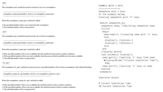
- 20. SEMAPHORE //SEMAPHORE Semaphore is a SystemVerilog built-in_class, used for access control to shared resources, and for basic synchronization. A semaphore is like a bucket with a number of keys. processes using semaphores must first procure a key from the bucket before they can continue to execute, All other processes must wait until a sufficient number of keys are returned to the bucket. Imagine a situation where two processes try to access a shared memory area. where one process tries to write and the other process is trying to read the same memory location. this leads to an unexpected result. A semaphore can be used to overcome this situation. //SEMAPHORE SYNTAX ==================== semaphore semaphore_name; //SEMAPHORE METHODS ====================== Semaphore is a built-in_class that provides the following methods, 1. new(); Create a semaphore with a specified number of keys 2. get(); Obtain one or more keys from the bucket 3. put(); Return one or more keys into the bucket 4. try_get(); Try to obtain one or more keys without blocking semaphore_name = new(numbers_of_keys); the new method will create the semaphore with number_of_keys keys in a bucket; where number_of_keys is integer variable. the default number of keys is ‘0’ the new() method will return the semaphore handle or null if the semaphore cannot be created
- 21. /put(); ======== The semaphore put() method is used to return key/keys to a semaphore. .-----------------------------------------------------------------. | semaphore_name.put(number_of_keys); or semaphore_name.put(); | '-----------------------------------------------------------------' When the semaphore_name.put() method is called, 1. the specified number of keys are returned to the semaphore. 2. The default number of keys returned is 1. //get(); ========= The semaphore get() method is used to get key/keys from a semaphore. .-----------------------------------------------------------------. | semaphore_name.get(number_of_keys); or semaphore_name.get(); | '-----------------------------------------------------------------' When the semaphore_name.get() method is called, 1. If the specified number of keys are available, then the method returns and execution continues 2. If the specified number of keys are not available, then the process blocks until the keys become available 3. The default number of keys requested is 1 //try_get(); ============= The semaphore try_get() method is used to procure a specified number of keys from a semaphore, but without blocking. .-------------------------------------------------------------------------. | semaphore_name.try_get(number_of_keys); or semaphore_name.try_get(); | '-------------------------------------------------------------------------' When the semaphore_name.try_get() method is called, 1. If the specified number of keys are available, the method returns 1 and execution continues 2. If the specified number of keys are not available, the method returns 0 and execution continues 3. The default number of keys requested is 1 EXAMPLE WITH 4 KEYS ================= Semaphore with 4 keys In the example below, Creating semaphore with ‘4’ keys module semaphore_ex; semaphore sema; //declaring semaphore sema initial begin sema=new(4); //creating sema with '4' keys fork display(); //process-1 display(); //process-2 join end //display method task automatic display(); sema.get(4); //getting '4' keys from sema $display($time,"tCurent Simulation Time"); #30; sema.put(4); //putting '4' keys to sema endtask endmodule Simulator Output 0 Current Simulation Time 30 Current Simulation Time
- 22. MAILBOX ================================ A mailbox is a communication mechanism that allows messages to be exchanged between processes. Data can be sent to a mailbox by one process and retrieved by another. Following is an example of declaring and creating a mailbox: mailbox mbxRcv; mbxRcv = new(); To place a message in a mailbox, two methods are supported put() (blocking) and peek() (nonblocking). To retrieve a message from mailbox, two methods are supported get() (blocking) and try_get() (nonblocking). To retrieve the number of messages in the mailbox, we can use num().
- 23. COVERAGE COVERAGE is: 1. Defined as the percentage of verification objective that have been met 2. Used as a metric for evaluating the progress of a verification project 3. Used to reduce the number of cycles spent in verifying a design 4. Allow the user to tell how well a design has been tested There are two types of coverage Code Coverage: 1. It checks the quality of testbench/inputs 2. Either code is wrong or testbench is wrong 3. Measure how much of the code has been executed 4. Code, Path, Expression, FSM Coverage are type of code coverage Functional Coverage: 1. User-specified to tie the verification environment to the design intent or functionality 2. Functional coverage goals are derived from the functional specification 3. Functional coverage is not automatically inferred from the design 4. It is user defined model
- 24. ============== //COVERGROUP ============== -> It is built-in .class -> The_covergroup construct encapsulate the specification of a coverage model and may contain: 1. A clocking event that synchronizes sampling of points 2. A set of coverage points 3. Cross coverage between coverage points 4. Optional formal arguments //CREATING COVERGROUP INSTANCES Example of a_covergroup definition covergroup cg_group; <definition of_covergroup> endgroup: cg_group 1. The_covergroup construct is a user-defined type 2. The type definition is written once 3. Multiple instances of that type can be created in different contexts _covergroup can be placed inside a module or a named block 4. Syntax for creating_covergroup instances cg_group = new(); =============== //COVERPOINTS =============== -> Coverpoints are the variables you are interested in tracking -> from these variablers you may be interested in tracking specific values or range of values -> During simulation the values for variables defined as coverpoints are tracked and stored in coverage database Syntax- --------- [coverpoint_id : ] coverpoint variable_id; OR [coverpoint_id : ] coverpoint variable_id {bins_defn}; Example- ---------- c1 : coverpoint address; c2 : coverpoint data;
- 25. 1) fork .. join: Processes that are created using “fork .. join” run as separate threads but the parent process that spawned them stall until a point where all threads join back together. If we look at the example below: there are three processes - task1, task2 and task3, that will run in-parallel and only after all three of these complete, the $display() after the join statement will execute. initial begin fork task1; // Process 1 task2; // Process 2 task3; // Process 3 join $display(“All tasks finished”); end 2) fork .. join_any: Processes that are created using “fork … join_any” run as separate threads but the parent process that spawned those stalls only until any one of the threads complete. Further, the remaining threads and the parent process can run parallely. If we look at the example below: there are three processes - task1, task2 and task3 that will run parallely. When one of task1/task2/task3 completes, the join_any will complete and cause the $display() to execute while other tasks might still be running. initial begin fork task1; // Process 1 task2; // Process 2 task3; // Process 3 join_any $display(“Any one of task1/2/3 finished”); 3) fork .. join_none: Processes that are created using “fork … join_none” run as separate threads but the parent process that spawned them doesn’t stall and also proceed parallely. Refer to the following example and there are three processes - task1, task2 and task3 that will run parallely with the parent process. initial begin fork task1; // Process 1 task2; // Process 2 task3; // Process 3 join_none $display(“All tasks launched and running”); end fork - join”, “fork - join_any” and “fork - join_none”
- 26. What is the difference between new() and new[] in SystemVerilog? The function new() is the class constructor function in SystemVerilog. It is defined in a class to initialize data members of the class. The new[] operator is used to allocate memory for a dynamic array. The size of the dynamic array that needs to be created is passed as an argument to the new[] . INTERVIEW QUESTIONS What are pre_randomize() and post_randomize() functions? These are built-in callback functions supported in SystemVerilog language to perform an action immediately either before every randomizecall or immediately after randomize call. A pre_randomize() is useful for setting or overriding any constraints while a post_randomize() is useful to override results of a randomization.
- 27. What are the main regions inside a SystemVerilog simulation time step?
- 28. Write constraints to create a random array of integers such that array size is between 10 and 16 and the values of array are in descending order? class array_abc; rand unsigned int myarray[]; endclass constraint c_abc_val { myarray.size inside { [10:16] }; foreach (myarray[i]) if (i>0) myarray[i] < myarray[i-1]; }
- 29. How can we use constraints to generate a dynamic array with random but unique values ? Refer the code below: class TestClass; rand bit[3:0] my_array[]; //dynamic array of bit[3:0] endclass There are two ways in which this can be done - one using the SV unique constraint and one without using it as shown in 2) below. 1) Add a unique constraint to the class as below constraint c_rand_array_uniq { my_array.size == 6; //or any size constraint unique {my_array}; //unique array values } 2) Without using unique constraint, you can still generate incremental values and then do an array shuffle() in post_randomize() ; constraint c_rand_array_inc { my_array.size == 6 ;// or any size constraint foreach (my_array[i]) if(i >0) my_array[i] > my_array[i-1]; } function post_randomize(); my_array.shuffle(); endfunction
- 30. Is it possible to override a constraint defined in the base class in a derived class and if so how? Yes, a constraint defined in the base class can be overridden in a derived class by changing the definition using the same constraint name. For Example: Refer the constraint c_a_b_const in following code. In the base class, it is defined to always have a value of a < b , but in a derived class, it has been overridden to have always a > b . class Base; rand int a ; rand int b; constraint c_a_b_const { a < b; } endclass class Derived extends Base; constraint c_a_b_const { a > b; } endclass
- 31. What is a virtual interface and where is it used? A virtual interface is a variable that points to an actual interface. It is used in classes to provide a connection point to access the signals in an interface through the virtual interface pointer. The following example shows an actual interface bus_if that groups a set of bus signals. A BusTransactor class then defines a virtual interface of this type that is used to access all signals from this bus_if for driving a request or waiting for a grant signal. The top level test module which instantiates the physical interface will pass the handle of same to the BusTransactor class through constructor which gets assigned to the virtual interface pointer. interface bus_if; // A bus interface logic req, grant; logic [7:0] addr, data; endinterface class BusTransactor; // Bus transactor class virtual bus_if bus; // virtual interface of type bus_if function new( virtual bus_if b_if ); bus = b_if; // initialize the virtual interface endfunction