Timer programming for 8051 using embedded c
Download as PPTX, PDF1 like2,016 views

The document discusses the timers and counters of the 8051 microcontroller. It describes that the 8051 has two 16-bit timers/counters that can be used as timers to generate delays or as event counters. These timers are accessed as two 8-bit registers - a low byte register (TL0/TL1) and high byte register (TH0/TH1). It also explains the timer mode register TMOD and provides code examples to use the timers for generating delays and frequencies.


Timer programming for 8051 using embedded c
- 1. DR. VIKAS J. DONGRE HOD ELECTRONICS & TELECOM GOVERNMENT POLYTECHNIC WASHIM (MS) EMAIL: [email protected]
- 2. The 8051 has two timers/counters, they can be used either as Timers to generate a time delay or as Event counters to count events happening outside the microcontroller Both Timer 0 and Timer 1 are 16 bits wide Since 8051 has an 8-bit architecture, each 16-bits timer is accessed as two separate registers of low byte and high byte
- 4. Accessed as low byte and high byte The low byte register is called TL0/TL1 and The high byte register is called TH0/TH1 Accessed like any other register MOV TL0,#4FH MOV R5,TH0 TH0 TL0 D15 D14 D13 D12 D11 D10 D9 D8 D7 D6 D5 D4 D3 D2 D1 D0 D15 D14 D13 D12 D11 D10 D9 D8 D7 D6 D5 D4 D3 D2 D1 D0 TH1 TL1
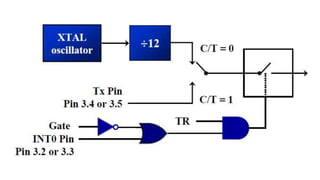
- 5. Both timers 0 and 1 use the same register, called TMOD (timer mode), to set the various timer operation modes TMOD is a 8-bit register The lower 4 bits are for Timer 0 The upper 4 bits are for Timer 1 In each case, The lower 2 bits are used to set the timer mode The upper 2 bits to specify the operation (MSB) (LSB) GATE C/T M1 M0 Timer1 GATE C/T M1 M0 Timer0
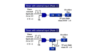
- 8. The following are the characteristics and operations of mode1: 1. It is a 16-bit timer; therefore, it allows value of 0000 to FFFFH to be loaded into the timer’s register TL and TH 2. After TH and TL are loaded with a 16-bit initial value, the timer must be started This is done by SETB TR0 for timer 0 and SETB TR1 for timer 1 3. After the timer is started, it starts to count up It counts up until it reaches its limit of FFFFH
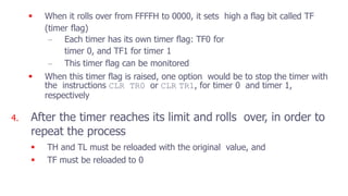
- 9. When it rolls over from FFFFH to 0000, it sets high a flag bit called TF (timer flag) – Each timer has its own timer flag: TF0 for timer 0, and TF1 for timer 1 – This timer flag can be monitored When this timer flag is raised, one option would be to stop the timer with the instructions CLR TR0 or CLR TR1, for timer 0 and timer 1, respectively 4. After the timer reaches its limit and rolls over, in order to repeat the process TH and TL must be reloaded with the original value, and TF must be reloaded to 0
- 10. 1. Load the TMOD value register indicating which timer (timer 0 or timer 1) is to be used and which timer mode (0 or 1) is selected 2. Load registers TL and TH with initial count value 3. Start the timer 4. Keep monitoring the timer flag (TF) with the JNB TFx,target instruction to see if it is raised Get out of the loop when TF becomes high 5. Stop the timer 6. Clear the TF flag for the next round 7. Go back to Step 2 to load TH and TL again To generate a time delay
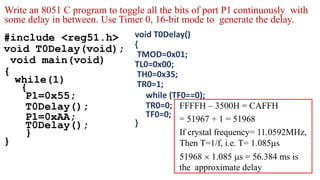
- 11. #include <reg51.h> void T0Delay(void); void main(void) { while(1) { P1=0x55; T0Delay(); P1=0xAA; T0Delay(); } } void T0Delay() { TMOD=0x01; TL0=0x00; TH0=0x35; TR0=1; while (TF0==0); TR0=0; TF0=0; } FFFFH – 3500H = CAFFH = 51967 + 1 = 51968 If crystal frequency= 11.0592MHz, Then T=1/f, i.e. T= 1.085s 51968 1.085 s = 56.384 ms is the approximate delay Write an 8051 C program to toggle all the bits of port P1 continuously with some delay in between. Use Timer 0, 16-bit mode to generate the delay.
- 12. Write an 8051 C program to create a frequency of 2500 Hz on pin P2.7. Use Timer 1, mode 2 to create delay. #include <reg51.h> void T1M2Delay(void); sbit mybit=P2^7; void main(void) { unsigned char x; while(1) { mybit=~mybit; T1M2Delay(); } } void T1M2Delay(void) { TMOD=0x20; TH1=-184; TR1=1; while (TF1==0); TR1=0; TF1=0; } 1/2500 Hz = 400 s 400 s /2 = 200 s 200 s / 1.085 s = 184
- 13. Assume that a 1-Hz external clock is being fed into pin T1 (P3.5). Write a C program for counter 1 in mode 2 (8-bit auto reload) to count up and display the state of the TL1 count on P1. Start the count at 0H. #include <reg51.h> sbit T01=P3^5; void main(void) { T01=1; TMOD=0x60; //01100000 TH1=0; while (1) { do { TR1=1; P1=TL1; } while(TF1==0); TR1=0; TF1=0; }}